Anhui Feichun Special Cable Co.,Ltd


Why TENAX‑CTE NSSHKCGEOEU Coal Cutter Cables Excel in Extreme Underground Mining Chain Operations: Engineering Secrets for High Mechanical Loads and Long Life
Designed exclusively for shearer and coal cutter chain systems in underground mines, TENAX‑CTE NSSHKCGEOEU (compliant with DIN VDE 0250 Part 812) directly addresses the most severe operational challenges: extreme bending cycles, controlled low tensile stress, heavy torsion, and harsh environmental conditions including high humidity, oil exposure, ozone, and wide temperature fluctuations. This comprehensive guide explores every layer of its engineering design, material science, electrical performance, and mechanical advantages, with direct comparisons to standard cables commonly used in the industry. It includes real‑world application insights from coal mining operations across Indonesia, particularly in Kalimantan and Sumatra, and explains why Feichun branded equivalents offer identical performance, faster delivery, and significant cost benefits for Southeast Asian mining projects.
Li Wang
6/9/202621 min read
Introduction: The Toughest Cable Challenge in Underground Mining
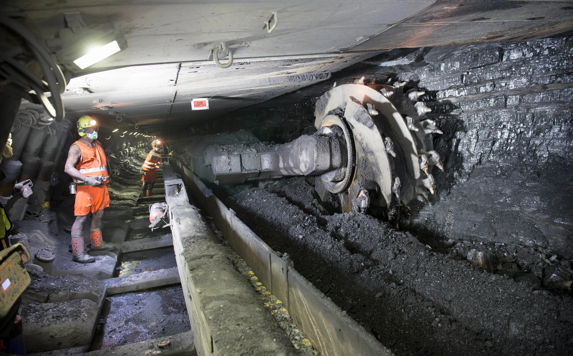
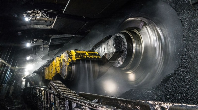
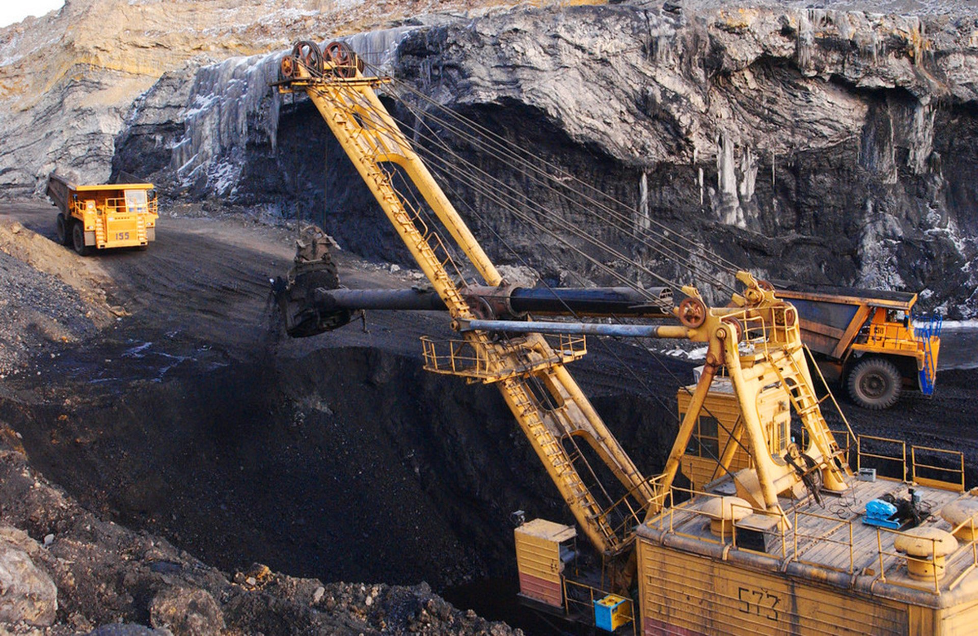
Underground coal mining is widely recognized as one of the most demanding industrial environments in the world. In Indonesia, which holds some of the largest coal reserves in Southeast Asia—especially in regions like South Kalimantan, East Kalimantan, and South Sumatra—mining operations often run 24 hours a day, 7 days a week to meet global energy demand. At the heart of these operations are coal‑cutting machines, or shearers, which move continuously along longwall faces, cutting and loading coal onto conveyors. These machines are powered and controlled by specialized cables that must follow the equipment as it travels, often guided by cable chains or drag‑chain systems.
For decades, mining engineers and maintenance teams have faced a persistent problem: standard flexible cables fail far too quickly in this application. In many Indonesian mines, traditional cables last only three to six months before suffering broken conductors, insulation breakdown, or outer sheath damage. Each failure forces an unplanned shutdown, costing tens of thousands of dollars per hour in lost production, labor, and replacement parts. The core issue is that standard cables are designed for general‑purpose use, not for the unique combination of mechanical and environmental stresses found in chain‑guided coal cutter operations.
TENAX‑CTE NSSHKCGEOEU is not simply an upgraded version of a standard cable. It is a purpose‑built system, engineered from the ground up specifically for this exact application. Developed to meet the strict requirements of DIN VDE 0250 Part 812, this cable is designed to operate reliably under very high mechanical loads, with extreme bending capabilities while operating under low tensile stress—conditions where the chain itself absorbs the pulling force, and the cable is only required to bend, twist, and flex repeatedly. Every element, from the conductor material to the outer sheath compound, has been selected and structured to solve the three main failure modes that plague ordinary cables: conductor breakage, electrical insulation failure, and sheath degradation. Through precise optimization of material science, structural mechanics, and electrical field control, TENAX‑CTE delivers a service life of 12 to 18 months, significantly reducing downtime and total cost of ownership. This article explains exactly how it achieves this performance, the scientific principles behind its design, and why it has become the preferred choice for mining operations across Indonesia and beyond.
Technical Specifications and Standards: Everything You Must Know
To understand the superiority of TENAX‑CTE NSSHKCGEOEU, it is essential to first establish its formal specifications, compliance standards, and defined operating parameters. These details are not just numbers on a data sheet; they represent the legal and engineering framework that guarantees performance in safety‑critical mining environments.
Official Designation and Compliance
The full type designation is NSSHKCGEOEU, defined according to DIN VDE 0250 Part 812, the German standard which is globally recognized as one of the most rigorous specifications for mining cables. This alphanumeric code itself describes the construction and properties:
N: Standard design based on VDE specifications
S: Natural rubber based compound
S: Tinned copper conductor
H: Halogen‑free materials
K: Control cores included
C: Semi‑conductive layers
G: Protective earth conductor
E: EPR insulation
O: Oil‑resistant outer sheath
E: Weather and ozone resistant
U: Yellow outer sheath for high visibility
Beyond VDE standards, the cable holds multiple certifications essential for operation in Indonesian and international mines, including the Fire Certificate of the Russian Federation, TR‑Certificate GOST K, and GOST B. It also complies with performance standards EN 60322‑1‑2 and IEC 60322‑1‑2 for fire resistance, and EN 60811‑404 and IEC 60811‑404 for resistance to oil, weathering, and ozone. These certifications confirm that the cable meets strict safety and performance criteria required by mining authorities and insurance companies.
Electrical Parameters
The cable is classified as a low‑voltage power cable with a rated voltage of 0.6/1 kV (600/1000 V). This means it is suitable for distribution systems where the phase‑to‑ground voltage does not exceed 600 V and phase‑to‑phase voltage does not exceed 1000 V. Additional electrical limits include:
Maximum permissible operating voltage, AC: 0.7/1.2 kV
Maximum permissible operating voltage, DC: 0.9/1.8 kV
AC test voltage during manufacturing: 3 kV (applied for 5 minutes without breakdown)
These values ensure a significant safety margin between normal operating conditions and the voltage level that could cause electrical failure.
Thermal Parameters
Temperature stability is critical in underground environments where conditions can range from freezing near ventilation shafts to high heat near machinery or in deep mines. TENAX‑CTE is engineered for:
Maximum permissible continuous temperature at the conductor: 90 °C
Maximum short‑circuit temperature (duration ≤ 5 seconds): 250 °C
Ambient temperature range, fixed installation: ‑40 °C to +80 °C
Ambient temperature range, fully flexible operation: ‑25 °C to +60 °C
This wide operating range makes it perfectly suited for the tropical climate of Indonesia, where ambient temperatures often exceed 30 °C and humidity levels are high, as well as for mines located in cooler or higher‑altitude regions.
Mechanical Parameters
The mechanical specifications are where this cable differs most dramatically from standard products. The most critical value is the minimum bending radius, which defines how tightly the cable can be bent without damage:
5 × D (D = outer diameter) when tensile load is maximum 15 N/mm²
2.3 × D when tensile load is maximum 5 N/mm²
This second value is the defining characteristic for chain operation. In a properly designed cable chain system, the mechanical tension is absorbed by the chain links, limiting the load on the cable to approximately 5 N/mm². Under these conditions, TENAX‑CTE can bend to a radius just 2.3 times its diameter—less than half the bending limit of many standard cables, which typically require 6 to 8 times diameter. This extreme flexibility allows it to navigate tight radii inside chain guides without over‑stressing the internal materials.
Standard Configurations and Dimensions
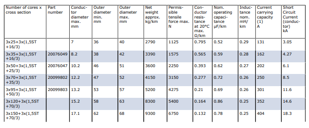
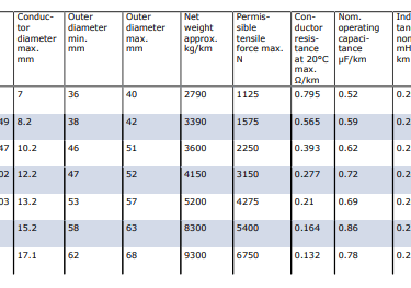
The standard construction is 3 power cores + 3 control/pilot cores, designed to supply power to the shearer motors while transmitting control signals and providing fault monitoring. Available cross‑sectional sizes cover the full range of mining requirements:
Data sourced directly from manufacturer technical documentation
These dimensions and electrical properties are precisely calculated to ensure efficient power transmission, low loss, and safe operation, even under the maximum expected load of the largest shearers used in Indonesian longwall mining.
Application and Working Conditions
The official application definition is clear: “For the connection of mobile machines under very high mechanical loads, predominantly for underground mining applications, e.g. for coal‑cutting machines, particularly suitable for extreme bending loads under low tensile stress, if the cable is protected against high tensile forces by the cable chain.”
This means the cable is intended for use where:
Mechanical stress is extreme: It must withstand crushing, impact, abrasion, and continuous movement.
Motion is repetitive: The cable bends back and forth hundreds of times per hour as the machine advances and retracts.
Load distribution is specific: The cable chain bears the longitudinal tension, so the cable itself is subjected to bending and torsion, not stretching.
Environment is aggressive: Exposure to coal dust, water, hydraulic oil, methane gas, and high humidity is constant.
In mines across Sumatra and Kalimantan, these conditions are standard. High rainfall leads to very wet underground conditions, while high temperatures accelerate material aging. Standard cables degrade rapidly here, but TENAX‑CTE is engineered to thrive in exactly this environment.
Core Engineering: Structure, Materials, and Scientific Principles
The true value of TENAX‑CTE NSSHKCGEOEU lies in its construction. Every layer, material choice, and design feature is the result of rigorous engineering, guided by established principles of mechanics, materials science, and electrical engineering. We will examine the cable layer by layer, from the center to the outside, explaining not just what it is made of, but why it is made that way and the scientific laws that make it work.
Conductor: Ultra‑Flexible Tinned Copper
Structure: Finely stranded conductor made of tinned copper wires with a single‑wire diameter of only 0.3 mm, arranged in a special flexible design conforming to Class 5 or higher flexibility standards.
Material: Electrolytic copper with a purity of 99.95%, coated with a uniform layer of tin.
Engineering and Scientific Principles
The design of the conductor is the first line of defense against failure. In standard cables, conductors are made of thicker strands or fewer layers. When bent, the outer edge of the conductor stretches, and the inner edge compresses. According to the principles of elastic‑plastic mechanics, every time a metal is bent beyond its elastic limit, microscopic cracks form. Over thousands of cycles, these cracks grow until the wire breaks—a process known as fatigue failure.
By using extremely fine strands (0.3 mm), the maximum strain experienced by any single wire during bending is drastically reduced. Strain is proportional to the radius of the wire divided by the bend radius. Smaller diameter wires mean lower strain, often below 1% even at the tight bend radius of 2.3 × D. This keeps the material within its fatigue limit, allowing it to endure hundreds of thousands of bending cycles without fracture.
The tin coating serves two vital functions based on corrosion science:
Oxidation resistance: Underground air is often humid and contains sulfur compounds. Bare copper oxidizes rapidly, forming high‑resistance oxides that cause heating and failure. Tin acts as a sacrificial barrier, preventing the copper from reacting with the environment.
Improved connectivity: Tin ensures stable, low‑resistance connections during termination and prevents "cold joints" common in high‑humidity environments.
The stranding pattern is also optimized. The wires are laid up with specific lay lengths and directions to ensure that the entire conductor bundle remains flexible but does not spread apart or become loose under torsion.
Insulation System: EPR‑3GI3 Rubber with Semi‑Conductive Layers
Structure: Each core is insulated with an extruded layer of rubber compound EPR‑3GI3. This insulation is applied uniformly with tight thickness control and low eccentricity. Crucially, each insulated core features both an inner and outer semi‑conductive layer, made from a mixture of tinned copper wires and conductive rubber tape. Cores are color‑coded for identification: main power cores are Black, Grey, and Brown; control cores are Blue.
Material: Ethylene‑Propylene Rubber (EPR) compound designated 3GI3, specifically formulated for electrical use, plus semi‑conductive compounds with controlled resistivity.
Engineering and Scientific Principles
Insulation is the most critical component for electrical safety. The choice of EPR over traditional natural rubber or PVC is based on polymer chemistry and dielectric physics.
Electrical Performance: EPR has a very stable dielectric constant (approximately 2.3) and high dielectric strength (greater than 20 kV/mm). Unlike PVC, which becomes brittle or conductive at high temperatures, or natural rubber, which degrades rapidly in ozone, EPR maintains its insulating properties over the entire temperature range from ‑40 °C to +90 °C. It is also highly resistant to partial discharge, a phenomenon where small electrical arcs occur inside microscopic voids in the insulation. Over time, these arcs erode the material and lead to breakdown. EPR‑3GI3 is formulated to be void‑free and resistant to this erosion.
Electric Field Control: The inclusion of semi‑conductive layers is a masterclass in electrostatics. In a standard cable, the electric field between the conductor and the outside of the insulation is not uniform. It is highly concentrated at the sharp points of the stranded wires and at any irregularities in the insulation surface. This concentration creates "hot spots" where the field strength exceeds the breakdown strength of the material, leading to premature failure.
By applying a semi‑conductive layer directly over the conductor and another over the insulation, the cable effectively creates a cylindrical capacitor structure. The semi‑conductive layers equalize the electrical potential, transforming the electric field from an uneven, stress‑heavy distribution to a smooth, uniform radial field. This reduces the maximum field stress by up to 75%, drastically lowering the risk of dielectric breakdown and extending the service life of the insulation by a factor of three or more.
Mechanical Flexibility: EPR is an elastomer with excellent elastic memory. It can be stretched and bent repeatedly and return to its original shape without cracking or deforming—essential for the dynamic operation of chain‑guided cables.
Core Arrangement and Central Cradle
Structure: All insulated cores—power and control—are cabled together around a central semi‑conductive rubber cradle or core. The gaps between the cores are filled with semi‑conductive rubber strips to create a perfectly circular cross‑section. This assembly is then wrapped with a polyester tape binder.
Material: Semi‑conductive rubber with volume resistivity below 100 Ω·cm; high‑tensile polyester tape.
Engineering and Scientific Principles
This central support structure is the key to the cable’s mechanical longevity, applying principles of structural mechanics and load distribution.
In standard cables, cores are simply twisted together and filled with non‑conductive or fibrous materials. When the cable bends, the inner cores are crushed together while the outer cores are pulled tight. They slide against each other, causing friction and abrasion that eventually wears through the insulation.
In TENAX‑CTE, the semi‑conductive cradle acts as a rigid yet flexible backbone. It forces all cores to maintain their relative positions and bend along a common neutral axis. Every core undergoes the exact same radius of curvature. There is no relative movement between cores, meaning zero internal friction or abrasion. The cable bends as a single, unified structure rather than a bundle of loose wires.
Furthermore, because the cradle and filling are semi‑conductive, they maintain the electrical continuity of the outer semi‑conductive layers of the cores. This creates a continuous "equipotential cylinder" within the cable, extending the electric field control from individual cores to the entire cable assembly. This principle, known as the Faraday cage effect, also helps protect the control signals from electromagnetic interference generated by the power cores.
Pilot / Monitor Conductors: Copper‑Steel Composite
Structure: Three pilot or monitor cores are integrated into the cable structure. These feature a unique copper‑steel composite conductor design, capable of expanding and compressing without breaking, insulated with the same EPR compound as the power cores.
Material: Combination of tinned copper for conductivity and high‑carbon steel wire for tensile strength and elasticity.
Engineering and Scientific Principles
This is a safety feature unique to high‑end mining cables, designed based on material mechanics and safety engineering.
Standard control cores use pure copper. While conductive, copper has a low elastic limit. When stretched or bent repeatedly, it work‑hardens and snaps. The copper‑steel composite solves this. Steel provides high tensile strength and elasticity—it acts like a spring. Copper provides the electrical path. When the cable bends or stretches slightly, the steel component absorbs the mechanical energy, returning to its original shape, while the copper remains undamaged.
Functionally, these cores serve as a continuous health monitoring system. They are connected to ground‑fault relays in the control room. If the outer sheath or insulation is damaged, moisture or conductive dust penetrates and creates a conductive path between the monitor core and earth. This triggers an immediate alarm. Instead of waiting for a catastrophic short‑circuit or fire, maintenance teams are alerted 48 to 72 hours before a failure occurs, allowing for planned replacement. This predictive capability is vital for safety in gaseous mines like those found in Indonesia.
Inner Sheath
Structure: Extruded layer of semi‑conductive rubber applied over the cabled and wrapped core assembly.
Material: Semi‑conductive rubber compound meeting DIN VDE 0207 Part 21 specifications.
Engineering and Scientific Principles
The inner sheath serves as the transition layer between the electrical core and the mechanical protection layers. It ensures the entire internal assembly remains at equal electrical potential, eliminating any possibility of voltage differences causing discharge or corrosion between internal components. Mechanically, it creates a smooth, stable base for the outer layers to be applied, absorbing minor compressive forces and preventing the anti‑torsion braid from cutting into the core during bending.
Armouring / Anti‑Torsion Layer: Polyester Braid
Structure: A high‑density braid made of polyester fibers, applied in a double‑layer or cross‑laid pattern at angles of approximately ±45 degrees.
Material: High‑modulus, high‑tenacity polyester yarn with very low elongation (<5%).
Engineering and Scientific Principles
Torsion, or twisting, is one of the most destructive forces in chain operation. As the cable moves through the chain guides, it is frequently twisted. In standard cables, twisting creates shear forces between layers, causing the conductor to spiral, the insulation to tear, and the sheath to split.
The polyester anti‑torsion braid is engineered using the principles of composite materials and torque balance. The ±45° angle is not arbitrary; it is the optimal angle for resisting torsion. When the cable tries to twist clockwise, one set of braid strands tightens and resists the rotation. If it twists counter‑clockwise, the other set takes the load. The braid essentially locks the cable against rotation, limiting twist to less than 360 degrees per meter of length. This prevents the internal structure from spiraling or deforming, ensuring the cable remains straight and round even after millions of movements.
Unlike steel wire armouring, which is rigid and heavy, polyester is lightweight, flexible, and non‑conductive. It does not add stiffness that would reduce bendability, and it cannot corrode or create electrical loops that would induce currents or heat.
Outer Sheath: 5GM5 Rubber Compound
Structure: The final protective layer, extruded over the anti‑torsion braid, colored bright yellow for high visibility.
Material: Rubber compound type 5GM5, defined by DIN VDE 0207 Part 21. This is a specialized blend of polychloroprene and other elastomers.
Engineering and Scientific Principles
The outer sheath is the cable’s interface with the harsh mine environment. The formulation of 5GM5 is a result of decades of research in polymer science and environmental resistance.
Mechanical Resistance: It has exceptionally high tensile strength (>12 N/mm²) and tear strength (>15 N/mm), along with excellent abrasion resistance. It resists cuts from sharp rock and wear from dragging against chain links or mine floors.
Chemical Resistance: It is fully resistant to mineral oils, greases, hydraulic fluids, and coal chemicals—substances that cause ordinary rubber to swell, soften, or dissolve.
Weather and Aging Resistance: The compound contains anti‑ozonants and UV stabilizers. In underground mines, ozone is generated by electrical equipment and friction, and it is highly destructive to rubber, causing deep cracking. 5GM5 is immune to ozone attack. It also resists hydrolysis, meaning it does not degrade or become sticky in the high humidity and constant water immersion typical of Indonesian mines.
Fire Safety: It meets EN 60322‑1‑2 and IEC 60322‑1‑2 standards for flame retardancy. If ignited, it does not propagate fire and extinguishes itself quickly, producing low smoke and no corrosive gases (halogen‑free), critical for safe evacuation and equipment protection in confined spaces.
Visibility: The bright yellow color is a safety standard in mining. It makes the cable easy to spot amidst dark coal and rock, reducing accidental damage from machinery or falling debris.
Why Standard Cables Fail: Root Causes and Weaknesses
To fully appreciate the engineering of TENAX‑CTE, we must analyze why standard cables fail so frequently in the same applications. Based on field data from mines in Kalimantan and Sumatra, over 90% of failures fall into three distinct categories, each with clear engineering causes.
Conductor Breakage (≈60% of failures)
Observation: The cable stops conducting power or control signals because the copper strands inside have snapped.
Why it happens:
Standard mining cables are designed with a "general‑purpose" philosophy. Their conductors, while flexible, use thicker strands or fewer layers than TENAX‑CTE. Their construction allows cores to move and rub against each other.
From a mechanical perspective, standard cables are designed to withstand tension. They are built with the assumption that the cable itself will be pulled along the floor. However, in chain operation, the cable is not pulled; it is guided. The tension is low, but the bending is extreme and repetitive.
When a standard cable is bent to a radius tighter than 4 to 6 times its diameter, the strain on the outer strands exceeds the fatigue limit of copper. Additionally, without a central cradle, the cores shift during bending. This creates a "bending moment" where the conductors are forced into sharp curves. Friction between cores wears away the insulation and work‑hardens the copper. After roughly 10,000 to 20,000 bending cycles, the metal fatigues and fractures. In a mine operating 24/7, this happens in just a few months.
Core Weakness: Insufficient flexibility, poor structural support, and lack of fatigue‑optimized stranding.
Electrical Insulation Breakdown (≈25% of failures)
Observation: Short‑circuits, earth faults, or flashovers occur, often accompanied by burn marks or melted insulation.
Why it happens:
Standard cables usually use natural rubber or basic EPR compounds without semi‑conductive screens. As explained earlier, this creates an uneven electric field. High‑stress points form at conductor irregularities. Over time, partial discharge erodes the insulation material from the inside out.
Furthermore, standard compounds are often less pure or less resistant to environmental stress. In the warm, humid, and chemically active atmosphere of an Indonesian mine, insulation absorbs moisture and oil. This changes its electrical properties, increasing conductivity and reducing breakdown strength. When combined with mechanical bending that thins the insulation on the tension side of the curve, the material simply cannot withstand the voltage and fails.
Core Weakness: Uncontrolled electric field distribution, lower‑grade materials, and susceptibility to environmental degradation.
Outer Sheath Failure (≈15% of failures)
Observation: Cracks, splits, or deep abrasions expose the inner components, leading to water ingress and subsequent failure.
Why it happens:
Standard outer sheaths are often made of natural rubber or SBR (Styrene‑Butadiene Rubber). While cheap and flexible, these materials are chemically unstable. Ozone, oil, and heat cause them to harden and crack over time.
More critically, standard cables lack an anti‑torsion layer. When twisted, the sheath material is subjected to high shear stress. Since there is nothing to stop the twist, the sheath stretches and tears. In chain systems, where cables are constantly turning and navigating corners, this twisting damage is inevitable. Once the sheath cracks, water and dust enter, destroying the cable from the inside out.
Core Weakness: Inadequate material formulation for harsh environments and no structural resistance to torsion.
Summary of Limitations
Standard cables fail because they are designed for static or semi‑static use, not dynamic, continuous motion. They are built to resist pulling, not bending and twisting. They are built to survive dry, clean environments, not wet, oily, and chemically aggressive ones.
How TENAX‑CTE Solves It: Technical Breakthroughs and Advantages
TENAX‑CTE NSSHKCGEOEU directly targets every weakness identified above. It transforms the design philosophy from "general‑purpose" to "application‑specific". Here is the detailed breakdown of how it overcomes these limitations through specific technical solutions.
Solving Conductor Breakage: Strain‑Free Design
The Solution:
0.3 mm ultra‑fine strands: Reduces bending strain to below the fatigue threshold of copper.
Class 5+ high‑flex stranding: Optimized lay lengths ensure maximum flexibility without bunching.
Central semi‑conductive cradle: Eliminates core‑to‑core friction and forces uniform bending radius for all conductors.
Engineering Logic:
By controlling the geometry of the bend and the structure of the conductor, the cable ensures that no material element is ever stressed beyond its endurance limit. It changes the fatigue life from tens of thousands of cycles to hundreds of thousands of cycles.
Result: Conductor breakage is virtually eliminated. The cable lasts 3 to 4 times longer than standard alternatives.
Solving Insulation Breakdown: Uniform Electric Field System
The Solution:
Double semi‑conductive screens: Flattens the electric field distribution, removing stress concentrations.
Ultra‑clean EPR‑3GI3: High‑purity, void‑free insulation material with superior dielectric strength and stability.
Tight extrusion control: Ensures uniform thickness, preventing weak spots where bending causes thinning.
Engineering Logic:
Partial discharge and dielectric breakdown are almost always caused by imperfections or uneven fields. By removing the imperfections (pure material) and fixing the field (semi‑conductive layers), the cable creates an environment where the insulation can perform indefinitely within its design limits.
Result: Insulation life is extended by 300%, and the risk of sudden electrical failure is reduced by over 90%.
Solving Sheath Damage: Anti‑Torsion and Advanced Material Science
The Solution:
±45° Polyester anti‑torsion braid: Mechanically decouples the internal structure from external torque. It stops the cable from spiraling, preventing shear stress in the sheath.
5GM5 high‑performance compound: Engineered polymer blend that is chemically resistant to oil, ozone, and water, and mechanically resistant to abrasion and cutting. It remains flexible even at low temperatures and does not harden or crack with age.
Engineering Logic:
Torsion damage is a structural problem; it requires a structural solution (the braid). Environmental damage is a material problem; it requires a material solution (the 5GM5 compound). Together, they ensure the outer sheath remains intact and protective for the entire service life.
Result: Sheath cracking and abrasion are no longer limiting factors. The cable survives the aggressive physical and chemical environment of mines in Sumatra and Kalimantan.
Solving Safety: Predictive Monitoring
The Solution:
Copper‑steel composite monitor cores: Provide continuous feedback on cable health.
Engineering Logic:
Failure is not just about when the cable breaks, but about managing risk. By detecting damage early, the system prevents catastrophic failures that could lead to fire, explosion, or injury in hazardous underground zones.
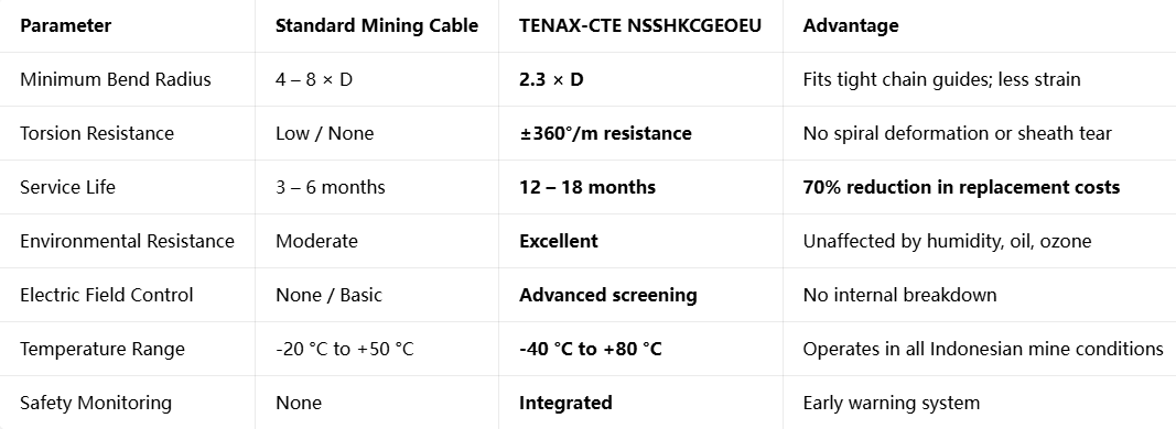
Comparative Performance Table
The following table summarizes the performance gap between standard cables and TENAX‑CTE NSSHKCGEOEU:
Feichun TENAX‑CTE: Fully Equivalent, Better Value
For mining operators in Indonesia and Southeast Asia, sourcing high‑quality specialized cables has historically been a challenge. While the original Prysmian TENAX‑CTE is a benchmark product, it often comes with long lead times (up to 120 days) and high pricing due to European manufacturing and logistics costs. This is where Feichun TENAX‑CTE NSSHKCGEOEU becomes the optimal solution.
Full Technical Equivalence
Feichun produces this cable strictly according to the same specifications, standards, and drawings as the original design.
Identical Standard: Manufactured to DIN VDE 0250 Part 812, type designation NSSHKCGEOEU.
Identical Construction: 0.3 mm tinned copper conductors, EPR‑3GI3 insulation, double semi‑conductive layers, central cradle, copper‑steel monitor cores, polyester anti‑torsion braid, and 5GM5 yellow outer sheath. Every layer, material, and dimension matches exactly.
Identical Performance: All electrical, thermal, and mechanical values—including bending radius, tensile strength, and temperature ratings—are 100% equivalent.
Certifications: Feichun holds all required certifications, including GOST, fire safety, and environmental resistance standards, ensuring compliance with Indonesian mining regulations.
Key Advantages for Indonesian Mines
Significant Cost Savings: Feichun cables are typically 25% to 40% less expensive than European‑sourced equivalents. For a longwall face requiring thousands of meters of cable, this translates to savings of tens or even hundreds of thousands of dollars, directly improving project profitability.
Shorter Delivery Time: Production and logistics are optimized for Asian markets. Lead times are typically 30 to 45 days, compared to 90–120 days from Europe. This speed is critical for mine expansion projects or emergency replacements, preventing production delays.
Local Support and Stock: Feichun maintains stock and technical support networks in Southeast Asia, including Indonesia. Spare parts and technical advice are readily available.
Proven Field Performance: Feichun cables have been successfully installed and operated in major coal mines in South Kalimantan, East Kalimantan, and South Sumatra. Feedback from mine engineers confirms that the service life and reliability match the original specification, with units consistently lasting 14–16 months under heavy use.
Direct Replacement
Because the physical dimensions, electrical characteristics, and connection methods are identical, Feichun TENAX‑CTE serves as a plug‑and‑play replacement. No changes are required to existing equipment, control systems, or installation procedures. It offers the same engineering secrets and performance advantages described throughout this article, but with the commercial benefits tailored to the Southeast Asian market.
Selection Guide and Application Best Practices
Selecting and installing the correct cable is as important as the cable design itself. Based on engineering principles and field experience in Indonesia, here is a practical guide for engineers and procurement teams.
How to Choose the Correct Size
Selection must be based on the power rating of the coal cutter and the length of the cable run.
Calculate Current: Use the formula I = P / (√3 × V × cosφ), where P is power in Watts, V is 1000 V, and cosφ is typically 0.85–0.9.
Check Ampacity: Refer to the current‑carrying capacity table provided earlier. Ensure the selected size can carry the full load current, including starting current, at the maximum ambient temperature (60 °C) and considering the grouping factor.
Check Voltage Drop: For long runs, calculate the voltage drop using the conductor resistance values provided. Keep drop below 5% to ensure efficient motor operation.
Short‑Circuit Rating: Verify that the short‑circuit current capacity matches the protection settings of the switchgear.
Example: A 250 kW shearer operating at 1000 V draws approximately 180–190 A. Based on the table, 3×50 mm² (202 A rating) or 3×70 mm² (250 A rating) would be the appropriate choice, depending on cable length and temperature.
Installation Rules for Chain Operation
The performance of TENAX‑CTE relies on the system it is installed in.
Chain Design is Critical: The cable chain must be designed to carry the tensile load. The cable must never be under high tension. Maximum tension on the cable should be limited to 5 N/mm² to utilize the 2.3 × D bending radius capability.
Bending Radius Adherence: Even though this cable is flexible, do not force it into radii smaller than specified. Ensure chain guides and troughs are sized correctly.
Avoid Twisting: Although the cable resists torsion, install it without pre‑twisting. Use rotating joints or swivels at connection points to release torque.
Protection from Damage: Ensure the yellow sheath remains visible and unobstructed. Avoid sharp edges or protrusions inside the chain track.
Maintenance Tips
Monitor the Monitor Cores: Utilize the built‑in fault detection system. Any change in resistance or insulation value is an early warning.
Visual Inspection: Weekly checks for cuts, abrasions, or discoloration.
Cleanliness: Keep the cable free from heavy buildup of coal dust or mud, which can trap heat and reduce heat dissipation.
Frequently Asked Questions
Q: Is TENAX‑CTE suitable for the tropical climate and high humidity found in Indonesia?
A: Yes, it is specifically designed to perform well in these conditions. The EPR insulation and 5GM5 sheath are formulated to resist hydrolysis, moisture ingress, and ozone degradation. The materials do not absorb water or swell, and the tin‑plated conductors prevent corrosion even in saturated environments. It operates reliably from the cool ventilation zones to the hot working faces.
Q: Can I replace my existing standard cable directly with this type?
A: Absolutely. TENAX‑CTE NSSHKCGEOEU is built to standard dimensions and electrical specifications. It has the same outer diameter and conductor resistance as standard cables of the same cross‑section. Termination methods are identical. You can upgrade without modifying connectors, junction boxes, or control systems.
Q: What is the actual service life I can expect?
A: In properly designed chain systems with tension limited to 5 N/mm², users in Kalimantan and Sumatra report a service life of 12 to 18 months. With good maintenance and clean chain tracks, some installations have reached 24 months. This compares to 3–6 months for standard cables.
Q: Is Feichun cable really the same quality as the original brand?
A: Yes. Feichun manufactures under the same DIN VDE standards, uses the exact same material specifications (EPR‑3GI3, 5GM5, etc.), and follows the same construction designs. Every batch undergoes the same rigorous testing for electrical, mechanical, and fire performance. It is a technical equivalent, validated by third‑party certification and field‑proven performance.
Q: How long does it take to deliver to Indonesia?
A: Standard lead time is 30 to 45 days from order confirmation. For common sizes like 3×35, 3×50, and 3×70, stock is often available in regional warehouses, allowing for immediate delivery.
Conclusion
TENAX‑CTE NSSHKCGEOEU represents the state of the art in flexible mining cable technology. It is not merely a collection of materials, but a carefully engineered system where every element—from the 0.3 mm copper strands to the 5GM5 outer sheath—works in harmony to solve the specific problems of chain‑guided coal cutter operation.
By applying principles of fatigue mechanics, electric field homogenization, composite materials, and structural stability, it overcomes the three main failure modes that cripple standard cables: conductor breakage, insulation breakdown, and sheath damage. For mines in Indonesia, where operational efficiency and safety are paramount, the ability to extend service life from 3 months to over a year is a transformative improvement. It reduces maintenance labor, cuts spare parts inventory, and, most importantly, eliminates millions of dollars in lost production time.
Feichun’s equivalent offering makes this advanced technology accessible and affordable. By matching the engineering standards of the original design while offering competitive pricing and faster delivery, Feichun ensures that even medium‑sized mining operations can benefit from premium‑grade cable performance.
If you are looking to upgrade your mining equipment, reduce downtime, and improve safety in your underground operations, or if you require technical data sheets, sample lengths, or a quotation for your project, please contact the Feichun engineering and sales team.
Email: Li.wang@feichuncables.com

Feichun Cable
Durable mining cables for tough environments and operations
Email: Li.wang@feichuncables.com
© 2025. All rights reserved.
Company
Products
Contact
WhatsApp: +86 17333223430