Anhui Feichun Special Cable Co.,Ltd


RHEYFESTOON (N)3GRD5G Cable Explained: Chemistry, Electromagnetics & Mechanical Engineering Behind High-Speed Festoon Systems
Explore the engineering behind RHEYFESTOON® (N)3GRD5G. Deep analysis of HEPR insulation, unshielded electromagnetics, mechanical dynamics & selection guide vs (N)3GRDGC5G.
Li Wang
4/27/202615 min read
Introduction
In the demanding worlds of material handling, port operations, mining, and heavy industry, the cable is far more than just a conductor. It is a critical moving component that must withstand extreme mechanical stress, rapid movement, and harsh environmental conditions while ensuring uninterrupted power delivery. The RHEYFESTOON® (N)3GRD5G represents a pinnacle of engineering design, specifically developed to meet these challenges. This guide explores the technology behind this cable, moving beyond simple specifications to understand the material science, electromagnetic principles, and mechanical dynamics that make it a preferred choice for high-performance applications.
What is RHEYFESTOON® (N)3GRD5G Cable?
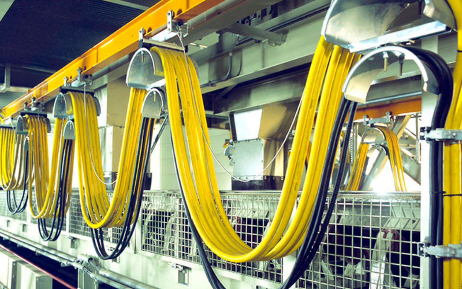
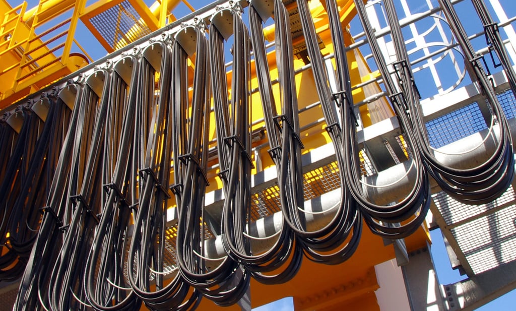
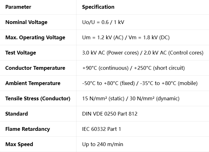
The RHEYFESTOON® (N)3GRD5G is classified as a flexible round festoon cable, designed for operation at a nominal voltage of 0.6/1 kV, capable of handling up to 1.2 kV in AC systems and 1.8 kV in DC systems. It is engineered specifically for heavy-duty applications where the cable is subject to continuous movement, tensile stress, and dynamic loads. Unlike standard fixed wiring cables, this product is built to move, bend, twist, and stretch reliably over millions of cycles.
Construction and Design
The cable structure is a result of careful material selection and geometric optimization. At the core lies the conductor, made of flexible plain copper strands classified as "FSC," which exceeds the requirements of IEC 60228 Class 5. This fine-stranded construction ensures excellent flexibility and resistance to fatigue caused by bending.
Surrounding the conductor is the insulation layer, composed of RHEYCLEAN-HEPR material. This high-performance compound surpasses the standards set in IEC 60502-1, providing superior electrical and mechanical properties. To provide additional mechanical support and protection, a special synthetic rubber inner sheath is applied, meeting or exceeding the EM6 standard according to prEN 50363. Finally, the cable is protected by an outer sheath formulated from EM7 rubber compound, offering robust resistance against external factors.
Technical Specifications
The performance of the cable is defined by a comprehensive set of parameters that govern its safe and effective use.
Core Identification and Standards
Clear identification of cores is essential for installation and maintenance. The cable follows the color coding standards of DIN VDE 0293 part 308 and HD 308 S2. For 4-core cables, the colors are green/yellow, brown, black, and grey. For 5-core designs, blue is added. In multi-core configurations exceeding 5 cores, the cores are black with white printed numbers, with the protective earth conductor always located in the outer layer. Every meter is clearly marked with "RHEYFESTOON (N)3GRD5G", cross-section area, voltage rating, and year of manufacture, carrying the VDE Registration Number 7891.
Why Unshielded Cables Dominate Pure Power Applications
The decision to use an unshielded design in the (N)3GRD5G is not a compromise on quality, but a strategic engineering choice optimized for power transmission. In applications where the primary function is to deliver high current energy rather than transmit sensitive data or control signals, the absence of a metallic shield offers distinct advantages.
Cost Efficiency and Simplicity
From an economic perspective, removing the shield layer significantly reduces the cost of raw materials and manufacturing complexity. A shield, typically made of copper tape or wire braid, adds substantial weight and material cost. By eliminating this layer, the overall project cost decreases without sacrificing the primary function of power delivery. Furthermore, installation becomes faster and simpler. Terminating an unshielded cable requires less time and no specialized techniques for grounding the screen, reducing labor costs and the potential for installation errors.
Mechanical Performance
The removal of the rigid metallic layer also enhances the cable's flexibility. In festoon systems operating at speeds up to 240 m/min, every gram of mass and every increase in stiffness matters. An unshielded cable is lighter and easier to bend, reducing the load on the towing mechanism and pulleys. This reduction in bending stiffness directly contributes to longer service life, as the internal components experience less mechanical friction and stress during movement.
Electrical Behavior
From an electrical standpoint, power systems operating at 50Hz or 60Hz are inherently less susceptible to electromagnetic interference compared to high-frequency data lines. The energy levels involved in power transmission are so high that minor external disturbances have negligible effect on the quality of the supply. Additionally, shielded cables can introduce unwanted phenomena such as circulating currents or capacitive coupling effects, which slightly reduce efficiency. In a pure power application, these losses are avoided, and the cable operates at maximum electrical efficiency.
HEPR Insulation: High Modulus Ethylene-Propylene Molecular Design
Insulation is the heart of any cable, and the use of HEPR (High Modulus Ethylene Propylene Rubber) in the RHEYFESTOON® series marks a significant advancement over traditional materials. Understanding the molecular architecture of this polymer reveals why it performs so well under extreme conditions.
The Polymer Backbone
HEPR is based on a copolymer of ethylene and propylene. By carefully controlling the ratio of these two monomers and the way they arrange themselves along the molecular chain, chemists can tune the physical properties of the final material. Ethylene segments tend to create areas of higher crystallinity and rigidity, while propylene units introduce irregularities that maintain amorphous, rubbery regions. The balance struck in HEPR creates a material that is tougher and stronger than standard EPR.
Understanding High Modulus
The term "High Modulus" refers to the material’s stiffness or resistance to deformation under load. In practical terms, this means that when the cable is bent or stretched, the insulation does not deform excessively. This property is crucial for maintaining consistent electrical properties throughout the cable's life. If the insulation were too soft, mechanical pressure could cause it to thin out over time, potentially leading to electrical breakdown. The high modulus ensures dimensional stability, keeping the conductor separation and wall thickness consistent even under mechanical stress.
Synergy of Properties
This molecular design results in a unique combination of features. The material retains excellent elasticity, meaning it can stretch and return to its original shape without permanent damage. Simultaneously, it possesses high tensile strength and resistance to cutting and abrasion. Electrically, HEPR exhibits very high insulation resistance and low dielectric losses, ensuring that energy is transmitted efficiently without leakage or heat generation. It is this combination of mechanical ruggedness and electrical excellence that makes HEPR the ideal choice for dynamic heavy-duty cables.
HEPR Vulcanization: Peroxide Crosslinking and Temperature Mechanics
The transformation of the HEPR compound from a soft, thermoplastic material into a durable elastomer is achieved through the process of vulcanization, specifically using peroxide crosslinking. This chemical reaction is what gives the cable its final thermal and mechanical properties.
The Crosslinking Mechanism
During manufacturing, the insulation is extruded onto the conductor and then passed through a continuous vulcanization tube. Inside, under conditions of high temperature and pressure, organic peroxides added to the compound decompose. This decomposition releases free radicals, highly reactive chemical species that attack the polymer chains. The radicals cause adjacent molecular chains to bond together, creating strong covalent Carbon-Carbon links.
The result is the creation of a three-dimensional network structure. Instead of long chains sliding past one another, they are now locked together at various connection points. This network is what defines an elastomer; it allows the material to stretch because the chains can uncoil, but the crosslinks prevent them from slipping apart completely, ensuring the material snaps back when the force is removed.
Temperature and Kinetics
The quality of the final product is heavily dependent on the temperature profile during curing. The reaction rate follows Arrhenius behavior, meaning that increasing the temperature significantly speeds up the process. However, temperature control is a delicate science. Insufficient curing, often called under-vulcanization, leaves the material soft and sticky with poor mechanical strength. Over-vulcanization, on the other hand, can lead to reversion or stiffening, making the insulation brittle and prone to cracking when flexed.
The engineering team precisely controls the heat zone temperatures to ensure full cure without degradation. The resulting network exhibits excellent resistance to high temperatures. While non-crosslinked plastics might melt or deform at 90°C or 100°C, the crosslinked HEPR remains stable and maintains its properties up to its rated temperature and beyond during transient overloads.
The 5G Sheath System: Synthetic Rubber Chemistry and Stabilizer Systems
While the insulation protects the electrical function, the outer sheath protects the entire cable from the outside world. The 5G sheath system employed here is based on advanced synthetic rubber chemistry designed to survive in the harshest environments.
Polymer Matrix Composition
The outer sheath utilizes a compound classified as EM7 according to European standards. This formulation is based on specialized polychloroprene or similar synthetic elastomers. The chemical composition is designed to provide a high degree of toughness. The polymer chains are formulated to resist mechanical wear, tear, and impact. Unlike simple plastics, this rubber compound remains flexible even at very low temperatures, preventing cracking in cold climates.
The Role of Stabilizers
A rubber compound is more than just polymer; it is a complex recipe of additives, and the stabilizer system is critical for long-term durability. Without protection, rubber would degrade rapidly due to oxygen, heat, and UV light.
Antioxidants are incorporated to interrupt the oxidation cycle that would otherwise cause the rubber to harden and crack over time. Heat stabilizers allow the material to operate continuously at elevated temperatures without losing elasticity. UV stabilizers and waxes form a protective barrier against sunlight and ozone attack. This is particularly important for outdoor applications where ozone, often generated by electrical equipment or pollution, can cause surface cracking in untreated materials.
Functional Performance
The combination of these chemical ingredients results in a sheath that is oil resistant, waterproof, and flame retardant according to IEC 60332-1. It acts as the first line of defense against chemical spills, sharp objects, and weathering, ensuring that the internal structure of the cable remains intact and protected for decades.
Electromagnetic Principles: Field Distribution and Crosstalk Physics
To fully appreciate the design choices, it is necessary to understand how electricity and magnetism behave within the cable. In an unshielded system like the (N)3GRD5G, electromagnetic fields operate differently than in shielded instrumentation cables.
Field Behavior
When current flows through a conductor, it creates an electric field and a magnetic field around it. In an unshielded cable, these fields are not contained; they extend outwards into the surrounding space. The electric field lines terminate on the surface of other conductors or grounded objects, while the magnetic field lines form concentric circles around the current path.
This open distribution is perfectly normal and safe. The insulation material is designed to withstand the electrical stress created by these fields, and the distance between conductors is calculated to prevent flashover or partial discharge. The energy is contained within the cable structure and the immediate surrounding air gap, functioning exactly as designed.
Understanding Crosstalk
Crosstalk occurs when the field from one cable or one core influences an adjacent one. This happens through two mechanisms: capacitive coupling, which relates to electric fields and voltage, and inductive coupling, which relates to magnetic fields and current.
In power applications, the concern is usually inductive coupling. However, because power cables typically carry balanced three-phase currents where the sum of the currents is ideally zero, their magnetic fields tend to cancel each other out over distance. Furthermore, the low frequency of 50/60Hz means that any induced interference is minimal and does not affect the operation of motors or heaters receiving the power. The physics demonstrate that for pure energy transmission, the natural cancellation effects and high signal energy make shielding unnecessary.
Grounding Systems and Electrical Safety
Safety is paramount in electrical design, and the behavior of the cable during fault conditions is a critical aspect of its specification. In unshielded cables, the concepts of ground loop impedance and zero-sequence currents are handled differently than in screened systems, yet safety remains fully compliant with international standards.
Ground Loop Impedance
The ground path in this cable design is provided by the dedicated protective earth core, which is sized to carry fault current safely. The impedance of this path is determined by the resistance of the copper conductor and the contact resistance at the termination points. Low impedance is vital because it ensures that during an earth fault, the current rises quickly to a level high enough to trigger circuit breakers or fuses, disconnecting the supply within milliseconds.
The design of the (N)3GRD5G ensures that the PE core is always positioned effectively within the cable geometry, and its cross-sectional area is calculated according to safety standards to handle the thermal and mechanical stresses of a short circuit.
Zero Sequence Currents
In three-phase systems, zero-sequence currents represent the sum of the instantaneous currents in all three phases. Under normal balanced load conditions, this sum is zero. However, during an earth fault, a zero-sequence current flows through the ground path.
In unshielded cables, this current flows exclusively through the dedicated earth wire and the external grounding network. This is a distinct advantage because it means there are no stray currents flowing through unintended paths or causing heating in metallic layers. The protection system can be set to detect this current accurately, ensuring selective coordination where only the faulty section of the plant is shut down, maximizing overall system availability.
Leakage Inductance: Shielded vs Unshielded Topologies
Inductance is a property of all electrical circuits, representing the ability to store energy in a magnetic field. Leakage inductance specifically refers to the flux that does not contribute to useful energy transfer but exists as a parasitic element in the system.
Comparative Analysis
In a shielded cable, the metallic screen acts as a magnetic barrier and a return path for flux. This tends to concentrate the magnetic field lines closer to the conductors, theoretically reducing the external field and the overall leakage inductance slightly. However, this comes at the price of increased capacitance between the core and the screen.
In an unshielded topology like the (N)3GRD5G, the magnetic field spreads more freely. Consequently, the leakage inductance is marginally higher than in an equivalent shielded design. However, for standard industrial power applications operating at mains frequency, this difference is electrically insignificant. It does not affect the motor performance or the power factor enough to be measurable in practice.
Practical Implications
The trade-off is clear. The slightly higher leakage inductance is vastly outweighed by the benefits of lower capacitance, lower cost, and better mechanical flexibility. In systems where long cables are used or high switching frequencies are involved (such as with VFD drives), the lower capacitance of unshielded cables can actually be beneficial in reducing dv/dt stress and reflected wave phenomena. Therefore, the topology is electrically optimized for its intended use case.
High-Speed Dynamics: Rheology and Mechanical Stress
One of the most impressive specifications of the RHEYFESTOON® cable is its ability to operate reliably at speeds up to 240 meters per minute. At these velocities, the mechanical forces acting upon the cable are severe, and material behavior shifts from simple elasticity to complex rheology.
Understanding Rheology
Rheology is the study of how matter deforms and flows under applied stress. At high speeds, the cable does not just bend; it is subjected to rapid acceleration, deceleration, torsion, and tension. The materials must behave predictably under these dynamic loads. The HEPR insulation and rubber sheaths possess ideal viscoelastic properties. They absorb energy like a viscous fluid but retain their structure like an elastic solid. This prevents the generation of excessive heat through internal friction, which is a common cause of failure in inferior cables.
Torsion and Stress Distribution
As the cable moves through festoon rollers or reels, it experiences twisting moments or torsion. This creates shear stresses within the material layers. The engineering design distributes these stresses evenly. The fine stranding of the conductor allows it to twist without creating high internal forces, while the high modulus of the insulation ensures that the core shape remains stable. The dynamic tensile strength of 30 N/mm² ensures that even under the high acceleration forces of rapid movement, the conductor will not stretch or break.
The combination of these properties means the cable can follow the movement of the machine precisely, without whipping, tangling, or suffering damage, ensuring smooth operation at maximum speed.
Lifespan Prediction: Fatigue and Crack Propagation
No material lasts forever, but understanding how and why failure occurs allows engineers to design for a specific service life. In dynamic cables, the primary failure mode is fatigue caused by cyclic loading.
The Fatigue Mechanism
Fatigue is a process where damage accumulates over time due to repeated stress applications, even if the individual stress levels are below the ultimate strength of the material. In the HEPR insulation, every bending cycle creates microscopic movements between the molecular chains and at the interface between the copper and the polymer.
Over time, if the material is not optimized, tiny voids or cracks can initiate at points of high stress concentration. These cracks grow slowly with each cycle until they reach a critical size, at which point electrical breakdown or mechanical split occurs.
Predicting Service Life
Engineers use S-N curves (Stress vs Number of cycles) to predict life expectancy. These curves show that the smaller the bending radius and the higher the dynamic load, the fewer cycles the cable will endure. The RHEYFESTOON® design pushes these limits significantly. The high-quality HEPR material has excellent resistance to crack initiation because the crosslinked network structure prevents the slippage and separation that leads to failure.
By testing under extreme conditions, manufacturers can guarantee performance over millions of bending cycles. The inclusion of specific fatigue-resistant additives and the careful control of extrusion adhesion ensure that cracks do not start easily, and once started, their propagation is slowed down dramatically. This translates directly into years of trouble-free service in the field.
Selection Guide: (N)3GRD5G vs. (N)3GRDGC5G
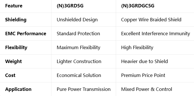
Choosing the right cable variant is essential for optimizing both performance and budget. The RHEYFESTOON® series offers two primary solutions that look similar but serve different technical requirements. The (N)3GRD5G is the unshielded version, while the (N)3GRDGC5G features a copper wire braided shield. Understanding the differences helps in making the correct decision.
Product Comparison
Decision Framework
The choice between these two models depends entirely on the operating environment and the function of the cable. The (N)3GRD5G is the logical choice when the application is dedicated solely to power distribution. In factories, ports, or mines where the cable runs alongside other power cables or in areas with low electromagnetic noise, the unshielded version performs perfectly. It offers the highest speed capability, the lowest weight, and the best price-to-performance ratio.
Conversely, the (N)3GRDGC5G is required in more complex electrical environments. If the cable contains both power cores and low-voltage control cores, or if it is installed near high-frequency converters, welding equipment, or high-voltage switchgear, the shield becomes necessary. The copper braid acts as a Faraday cage, preventing external noise from corrupting sensitive control signals and stopping the power cable from emitting interference that might affect other devices. When signal integrity is as important as power delivery, the shielded variant is the correct investment.
Case Study: Success in Indonesia
Real-world performance is the ultimate test of engineering. A major infrastructure project in Indonesia demonstrates how the RHEYFESTOON® cable performs under extreme tropical conditions. The project involved large-scale material handling equipment operating in a humid, coastal environment where temperatures often exceed 30°C and salt air corrosion is a constant challenge.
Project Requirements
The application required cables capable of high-speed festoon movement combined with long travel lengths. The environment demanded excellent resistance to UV radiation, as the equipment operated outdoors under intense equatorial sunlight. Furthermore, the presence of industrial pollutants and moisture meant that standard cables would degrade rapidly, leading to downtime and high maintenance costs.
Implementation and Results
The decision was made to install the RHEYFESTOON® (N)3GRD5G. The HEPR insulation and EM7 sheath combination proved ideal for the climate. The UV stabilizers in the sheath compound prevented surface cracking and hardening, while the hydrophobic nature of the rubber repelled water and resisted the humid atmosphere.
Mechanically, the cable handled the high-speed operations without issue. The high modulus insulation maintained its shape and electrical strength despite the constant flexing. Since installation, the system has operated continuously with zero cable-related failures. The client reported significant savings compared to previous solutions, not only in terms of purchase price but also in reduced maintenance and extended service life. This case validates that the material science and design principles translate directly into reliability in harsh operating conditions.
Frequently Asked Questions
Can this cable be used for direct burial or underwater applications?
The RHEYFESTOON® (N)3GRD5G is designed for festoon and trailing applications where it is supported or moved freely. While the sheath is highly waterproof and resistant to moisture, it is not specifically designed for permanent direct burial without additional protection or ducting. For submerged applications, specific submersible cables should be considered, although the (N)3GRD5G can withstand temporary water contact and outdoor weathering perfectly well.
What is the minimum bending radius I should observe?
The bending radius is defined according to DIN VDE 298 standards. For installation and handling, a larger radius is recommended to avoid damaging the new cable. During operation, the minimum radius is typically 5 times the outer diameter of the cable. Adhering to this radius ensures that the insulation is not excessively stressed and that the conductor strands do not suffer from mechanical fatigue or distortion.
How are the cores identified?
Core identification follows strict European color standards. For 4-core cables, the colors are green/yellow, brown, black, and grey. For 5-core cables, blue is added to this sequence. For cables containing more than 5 cores, the identification system switches to black insulation with white printed numbers, ensuring easy reading even in low light. The protective earth core is always positioned on the outer layer for easy recognition and safety.
Is the material halogen-free?
The standard (N)3GRD5G utilizes a rubber compound based on EM7 specifications which provides excellent flame retardancy according to IEC 60332-1. If specific Low Smoke Halogen Free (LSHF) requirements are needed for tunnels or enclosed spaces, variants of this cable are available with modified compound formulations to meet those specific environmental and safety demands.
What is the expected service life?
Service life depends heavily on the application factors such as bending radius, speed, temperature, and load cycles. However, under normal recommended operating conditions, this cable is designed to last for many years. The crosslinked HEPR insulation does not age easily like thermoplastic materials, and the robust sheath resists weathering. It is not uncommon for these cables to remain in service for a decade or more in heavy industrial use.
Conclusion
The RHEYFESTOON® (N)3GRD5G is far more than a simple electrical component; it is a sophisticated system engineered at the molecular level. From the high-performance HEPR insulation chemistry to the electromagnetic behavior of the unshielded design, and from the dynamic mechanical properties capable of 240 m/min operation to the robust protection of the 5G sheath system, every aspect is designed for reliability.
Understanding the engineering principles behind this cable allows users to appreciate why it performs so well and how to select the right variant for their specific needs. Whether operating in the freezing cold or the intense heat, at slow speeds or maximum velocity, this technology ensures that power flows reliably, keeping industry moving.
If you are looking to purchase this cable or require technical advice for your specific project, our engineering team is ready to assist you. We provide detailed specifications, custom lengths, and support for global projects.
Email: Li.wang@feichuncables.com
Feichun Cables – Engineering Reliability for Extreme Environments.
Feichun Cable
Durable mining cables for tough environments and operations
Email: Tech@feichuncables.com
© 2025. All rights reserved.
Company
Products
Contact
WhatsApp: +86 13855123218