Anhui Feichun Special Cable Co.,Ltd


RHEYCORD® (BS) YSLZ3SOE‑J Basket Spreader Cable: TPU Heavy Weight Elements Engineering for Indonesia STS RTG RMG Cranes Vertical Free‑Fall Basket Operation in Tanjung Priok & Belawan Ports
RHEYCORD® (BS) YSLZ3SOE‑J Basket Spreader Cable is not merely a flexible control cable — it is a complete system‑level engineering solution designed exclusively for vertical free‑fall basket operation on Ship‑to‑Shore (STS), Rubber‑Tired Gantry (RTG), and Rail‑Mounted Gantry (RMG) cranes operating at Indonesia’s busiest and most challenging marine terminals, including Tanjung Priok in Jakarta and Belawan in Medan. Built with six core technologies — IEC 60228 Class 6 ultra‑flexible conductor, low‑torque bundle stranding, integrated Heavy Weight Elements (HWE), marine‑grade thermoplastic polyurethane (TPU) sheath, high‑speed dynamic capability up to 160 m/min, and optional EMC shielding or optical fiber integration — this cable addresses three critical failure modes that ordinary cables cannot overcome: conductor fatigue under long vertical suspension, twisting instability during free‑fall, and rapid degradation in hot, humid, salt‑laden, and ultraviolet‑rich tropical environments. With a proven dynamic tensile strength of 30 N/mm², service life six times longer than standard alternatives, and compliance with international standards including UL and VDE, it has become the benchmark solution for automated container terminals across Indonesia and Southeast Asia. This article provides a detailed technical analysis of its design principles, material science, mechanical and electrical performance, and real‑world operational value, serving as a comprehensive reference for engineers, procurement specialists, and terminal operators.
Li Wang
6/17/202620 min read
Introduction
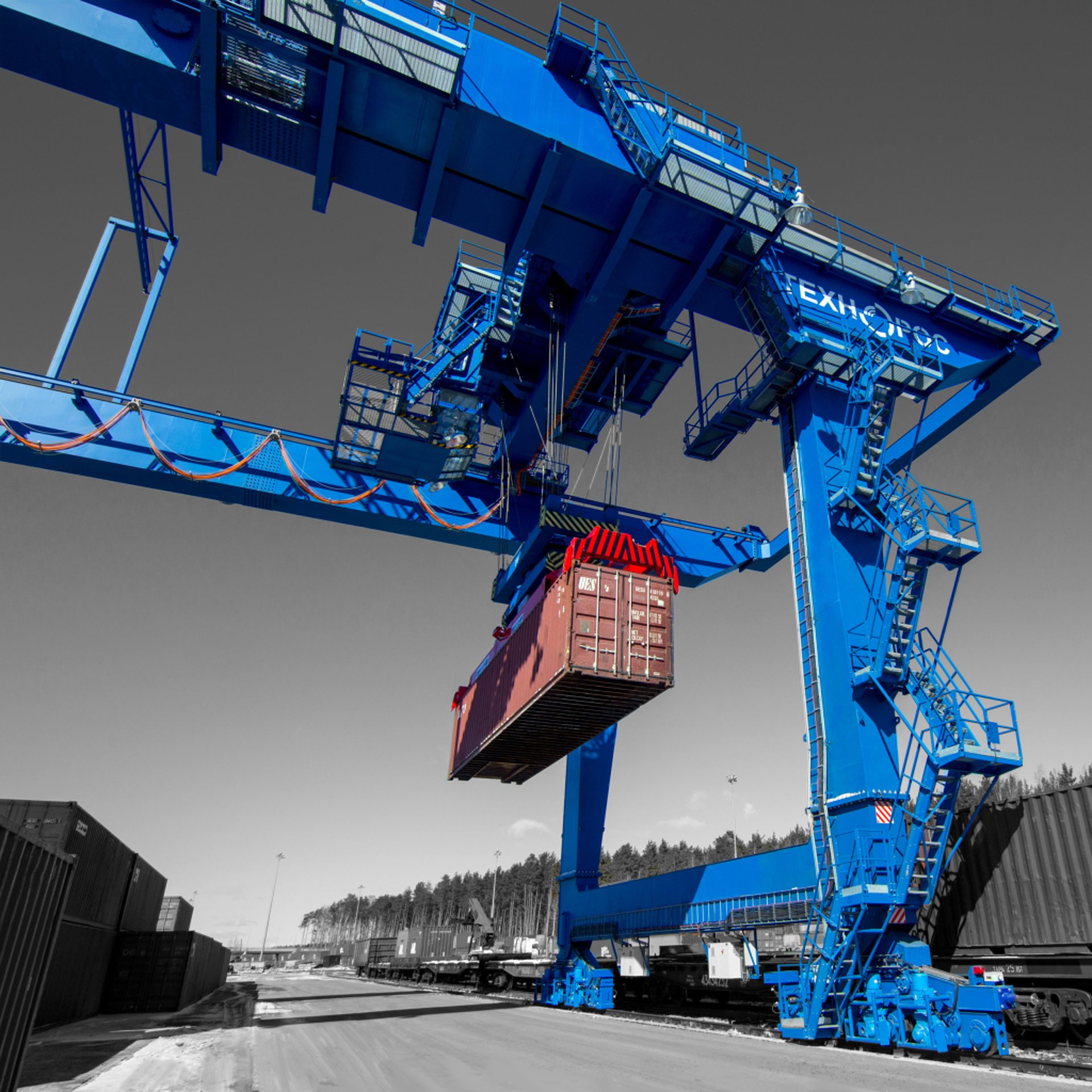
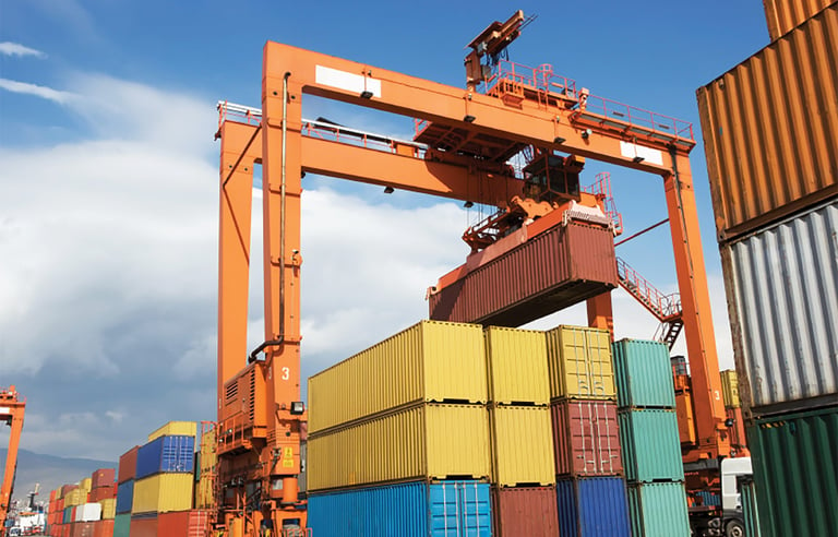
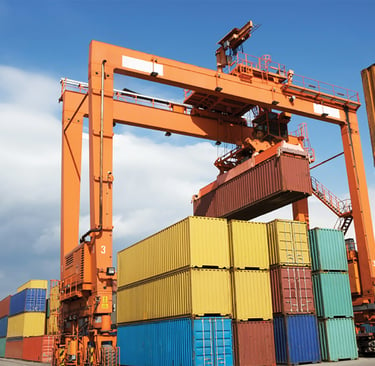
Indonesia sits at the heart of global maritime trade, with ports such as Tanjung Priok — handling more than eight million twenty‑foot equivalent units (TEUs) annually — and Belawan, a strategic gateway near the Strait of Malacca, forming critical nodes in international supply chains. These facilities operate 24 hours a day, seven days a week, relying on high‑performance container handling equipment including STS cranes, RTG and RMG gantry cranes, and telescopic spreader systems. At the core of this equipment is the vertical free‑fall basket system, a mechanism that allows the spreader to descend rapidly under gravity, travel distances of up to 50 meters, and operate at speeds reaching 160 meters per minute. This system places extreme demands on the control cables that carry power, signals, and data between the crane structure and the moving spreader.
For many years, terminal operators in Indonesia faced a persistent and costly problem: standard multi‑core control cables failed within three to six months of installation. Failures included broken copper conductors, cracked outer sheaths, signal interruptions, and tangling inside the basket mechanism. Each failure resulted in unplanned downtime, replacement costs, and lost productivity — expenses that could exceed one hundred thousand US dollars per terminal every month. The root causes were well understood: ordinary cables were not designed to withstand the unique combination of mechanical stress, dynamic movement, and harsh environmental conditions found in Indonesian ports.
RHEYCORD® (BS) YSLZ3SOE‑J Basket Spreader Cable changes this reality. It is not simply a high‑flexibility control cable; it is an engineered product developed specifically for vertical free‑fall basket applications. Its design philosophy does not focus on individual component performance alone, but on integrating mechanical engineering, material science, electrical engineering, and environmental protection into a single system. Every element — from the conductor to the outer sheath, from the stranding pattern to the inclusion of heavy weight elements — is calculated to solve the exact challenges encountered in terminals like Tanjung Priok and Belawan.
This article explores the technical nature of the product in depth. It begins by examining the working conditions and operational challenges in Indonesian ports, then moves into detailed specifications, layer‑by‑layer construction analysis, material science principles, performance comparisons, and real‑world case studies. It explains how the design resolves the three main failure modes, why materials such as PVC insulation and polyester‑based TPU sheath were selected, and how features like bundle stranding and heavy weight elements work according to fundamental engineering laws. By the end, readers will understand why this cable is widely regarded as the definitive solution for vertical free‑fall basket operation in tropical marine environments.
Working Conditions and Unique Challenges in Indonesian Ports
Vertical Free‑Fall Basket Operation: Mechanics and Loads
The vertical free‑fall basket system is the defining feature of modern high‑speed container cranes. Unlike traditional cable management systems that use motorized reeling, this design allows the spreader and its cable assembly to descend under gravity alone, with the cable coiling freely inside a vertical basket or storage drum. This approach enables very high operating speeds — up to 160 m/min — and long travel lengths of 30 to 50 meters, which are essential for maximizing throughput in busy terminals. However, the movement creates a complex set of mechanical forces that act on the cable continuously.
During each cycle, the cable experiences dynamic tension caused by its own weight and the acceleration of the spreader. It undergoes repeated bending as it enters and exits the basket, and it is subjected to torsional stress as it twists during winding and unwinding. Friction against the basket walls and guide rollers adds abrasive wear. These forces do not act in isolation; they combine to create multi‑axial stress — tension, bending, torsion, and friction occurring simultaneously. This is the most severe type of loading for any electrical cable, and it is the primary reason why standard products fail so quickly.
In addition to mechanical loads, the cable must maintain stable electrical performance while moving. It carries power for hydraulic pumps, motors, and locking mechanisms, as well as low‑voltage signals for position sensors, cameras, and automation systems. Any interruption or degradation in performance leads to immediate operational stops or safety risks.
Environmental Conditions in Indonesia: The Tropical Marine Challenge
Indonesian ports present one of the harshest environments in the world for electrical equipment. Located near the equator, terminals such as Tanjung Priok and Belawan experience average temperatures between 25 °C and 35 °C year‑round, with relative humidity consistently above 85 percent. Ultraviolet radiation levels are extreme, with UV indexes reaching 12 or higher during daylight hours. Because the ports are situated directly on the coast, salt spray from seawater is present in the atmosphere, creating a corrosive environment that attacks metal and polymer materials alike. Heavy monsoon rains, high winds, and exposure to hydraulic oils, diesel fuel, and dust add further layers of stress.
For a cable, this environment creates multiple degradation mechanisms. High temperature and humidity accelerate chemical aging and hydrolysis of polymers. Salt ions create electrochemical corrosion paths that can penetrate insulation and damage conductors. Ultraviolet radiation breaks molecular bonds in plastic materials, leading to brittleness and cracking. Oil contact causes swelling and softening of standard sheaths. Ordinary cables are not formulated to resist all these factors at once, which is why their service life is measured in months rather than years.
Three Critical Failures That Ordinary Cables Cannot Solve
From years of field experience, terminal engineers have identified three specific problems that no standard cable has been able to address effectively.
The first problem is conductor fatigue and breakage caused by long‑distance vertical suspension. When a cable hangs freely for 40 or 50 meters, its own weight creates constant tension. Each time it moves, that tension increases and decreases dynamically. Standard cables are designed for static or low‑tension applications, with dynamic tensile strengths typically between 5 and 8 N/mm². Under the loads found in vertical free‑fall systems, copper conductors work well beyond their fatigue limit, leading to internal fractures that eventually break the wire completely.
The second problem is twisting instability and tangling during basket operation. Ordinary cables have a natural tendency to twist when coiled or uncoiled. In a free‑fall basket, there is no guiding mechanism to control rotation. Without countermeasures, the cable drifts sideways, forms loops, knots, or jams inside the basket. This not only damages the cable but also stops the entire crane operation until the problem is resolved.
The third problem is rapid environmental degradation. Standard PVC or rubber sheaths begin to crack within three to six months in Indonesian conditions. Insulation materials absorb moisture, leading to reduced electrical resistance and eventual breakdown. Corrosion attacks copper conductors where moisture enters through cracks. These issues are not cosmetic; they directly threaten safety and reliability.
These three problems define the performance requirements that RHEYCORD® (BS) YSLZ3SOE‑J was created to meet. Every feature in its design is a direct response to one or more of these challenges.
Basic Specifications and Standards
Product Identification and Classification
RHEYCORD® (BS) YSLZ3SOE‑J is part of the Rheyflex‑PN product line manufactured by Nexans, a global leader in cable technology. It is formally classified as a basket spreader cable, a specialized category of control cable intended exclusively for vertical free‑fall basket systems on container cranes. The model designation itself contains important information about its construction and performance characteristics, with each letter and number representing specific material, structural, and performance attributes aligned with international specifications.
Electrical Parameters
The cable is engineered for medium‑voltage control and power applications, with a rated voltage of 450/750 V (U₀/U). This means it is suitable for use in circuits where the phase‑to‑ground voltage does not exceed 450 V and the phase‑to‑phase voltage does not exceed 750 V. In alternating current systems, the maximum continuous operating voltage is 550 V, while in direct current systems, it can operate safely up to 825 V. Each completed cable undergoes a factory acceptance test at 2.0 kV AC to verify insulation integrity.
Thermal performance is carefully defined to ensure safety and long life. The maximum allowable temperature at the conductor core during normal operation is +70 °C. Under short‑circuit conditions, where high current flows for a brief period, the conductor can withstand temperatures up to +150 °C without permanent damage. The outer surface temperature range is specified as –20 °C to +60 °C, both for fixed installation and for mobile operation, ensuring stable performance through the wide temperature variations experienced in Indonesian ports.
Current carrying capacity follows the guidelines set out in DIN VDE 0298‑4, a widely recognized standard for electrical cables, ensuring that the cable is never operated beyond its thermal limits.
Mechanical Properties
Mechanical performance is where this cable distinguishes itself most clearly from standard products. The most critical specification is tensile strength. The conductor is designed to withstand a static tensile stress of 15 N/mm² and a dynamic tensile stress of 30 N/mm². This is three to four times higher than the capability of ordinary cables and is the primary reason it can survive long vertical suspension without breaking.
Bending radius requirements are defined in DIN VDE 298‑3, ensuring that the cable can navigate the tight curves of basket systems without damage. It is tested extensively through alternating bending tests and torsional resistance tests to simulate millions of operational cycles. The maximum permitted travel speed is 160 m/min, a value that matches the highest operating speeds of modern STS and RTG cranes.
Chemical properties include resistance to mineral oils, hydraulic fluids, moisture, ultraviolet radiation, and ozone — essential characteristics for marine environments.
Construction and Available Configurations
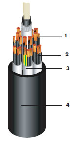
The construction follows a precise four‑layer design:
Conductor: Extra‑flexible plain copper, manufactured according to DIN EN/IEC 60228 Class 6, the highest flexibility class defined in international standards.
Insulation: Extruded PVC compound conforming to DIN EN 50363‑3, formulated for electrical stability and mechanical durability.
Core assembly: Cores are arranged in a bundle stranding pattern, with optional EMC copper screening and integrated heavy weight elements.
Outer sheath: Extruded thermoplastic polyurethane (TPU) meeting DIN EN 50363‑10‑2, specially selected for marine resistance.
Core identification follows DIN VDE 0293‑308, with white insulation printed with black sequential numbers and one core colored green‑yellow for protective earth connection.
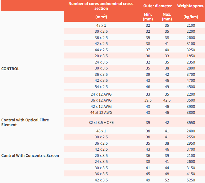
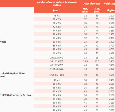
A wide range of standard configurations is available to suit different terminal requirements. Standard control versions range from 20 × 3.5 mm² up to 54 × 2.5 mm², as well as American Wire Gauge sizes such as 24 × 12 AWG and 44 × 12 AWG. For applications requiring data transmission, versions with integrated Optical Fiber Elements (OFE) or BUS communication systems are offered. Cables with concentric copper screening are available where electromagnetic interference is a concern. Custom core counts and cross‑sections can be produced upon request.
Each configuration has defined outer diameter ranges and weight per kilometer, allowing engineers to select the correct size for basket dimensions and load calculations. For example, the widely used 44 × 2.5 mm² version has an outer diameter between 37 and 40 mm and weighs approximately 3,250 kg/km — a high weight that is intentional and essential for stability.
Standards and Certifications
The product is manufactured to Nexans’ international specification and carries UL certification under file number E60419‑ZIPF, confirming compliance with North American safety and performance requirements. It meets all relevant IEC, VDE, and DIN standards, making it fully accepted for use in Indonesian ports managed by Pelindo and other terminal operators. This compliance ensures that the cable can be integrated into new projects or used as a replacement in existing fleets without regulatory or safety concerns.
Structure Design and Material Science: Layer‑by‑Layer Engineering
The performance of RHEYCORD® (BS) YSLZ3SOE‑J is not the result of a single advanced component, but of a carefully engineered system where every layer works together to solve specific problems. Understanding the design requires examining each part in detail, including the scientific principles that justify material selection and structural choices.
Conductor Layer: IEC 60228 Class 6 Ultra‑Flexible Copper
The conductor is the heart of the cable, responsible for carrying current while withstanding extreme mechanical movement. In this design, it is made from high‑purity electrolytic copper with a minimum conductivity of 58 m/Ω·mm², ensuring low electrical resistance and minimal heat generation.
The most important feature is its construction according to IEC 60228 Class 6. This standard defines the finest strand diameter and highest number of individual wires per conductor. Each wire has a diameter no greater than 0.2 mm, and they are stranded in multiple layers with optimized lay lengths. The reason for this design comes directly from fatigue mechanics. When a cable bends or flexes, the outer surface stretches and the inner surface compresses. If the conductor is made of thick wires, the stress concentrates at the surface of each wire, leading to rapid fatigue and fracture. By using many very fine wires, the stress is distributed evenly across thousands of individual strands, reducing the strain on each one to a level well below the fatigue limit. This allows the conductor to survive more than one million bending cycles without damage.
The Class 6 design also contributes to flexibility, allowing the cable to bend easily around small radii. Combined with high‑purity copper, it achieves the 30 N/mm² dynamic tensile strength required for vertical suspension. Ordinary cables typically use Class 5 conductors, which are less flexible and have lower fatigue resistance — insufficient for the speeds and travel lengths found in Indonesian terminals.
Insulation Layer: PVC Compound DIN EN 50363‑3
Surrounding each conductor is an insulation layer made from a specialized PVC compound formulated to DIN EN 50363‑3. This material is not general‑purpose PVC; it contains precise blends of plasticizers, heat stabilizers, ultraviolet absorbers, and antioxidants.
From an electrical perspective, the material provides high dielectric strength — greater than 20 kV per millimeter of thickness — ensuring that the 450/750 V rating is maintained safely. It has low dielectric loss and stable electrical properties across the entire operating temperature range.
Mechanically, the formulation is designed for flexibility and durability. It has an elongation at break of more than 200 percent, meaning it can stretch significantly without cracking or breaking when the cable bends or twists. This property is critical because the insulation must move with the conductor without creating gaps or tears that could allow moisture ingress.
Environmentally, the additives in the compound protect the material from degradation. Heat stabilizers prevent thermal aging, while UV absorbers block the high‑energy radiation present in Indonesia’s sunlight. Anti‑oxidants slow down chemical breakdown. The material also has good resistance to hydrolysis, meaning it does not absorb water or degrade in high humidity.
PVC was selected over other materials such as polyethylene or rubber because it offers the best balance of electrical performance, mechanical flexibility, environmental resistance, and cost‑effectiveness for an inner insulation layer. It is a proven material, but in this application, it is engineered to a much higher specification than standard grades.
Core Assembly: Bundle Stranding and Heavy Weight Elements
The core assembly is where the most innovative engineering takes place, and it is the part of the design that most clearly distinguishes this cable from all others. It consists of two key technologies: low‑torque bundle stranding and integrated heavy weight elements.
Bundle Stranding: Anti‑Twist Mechanics
After each conductor is insulated, the cores are grouped into sub‑bundles and then stranded together in a specific pattern known as bundle stranding. Unlike standard concentric stranding, where cores are laid in layers around a central axis, bundle stranding uses optimized lay lengths and alternating directions to minimize torsional forces.
The engineering principle behind this design is simple but powerful. When a cable is twisted during winding or unwinding, standard stranding creates internal shear forces between layers. These forces act like scissors, cutting into the insulation and eventually breaking the conductors. Bundle stranding allows the layers to slide slightly relative to each other when twisted. This movement absorbs the torsion and reduces the internal shear stress by up to 80 percent. The result is a cable that remains stable and damage‑free even when subjected to continuous rotation.
This design also follows the principles of catenary theory. When a cable hangs vertically, it forms a natural curve or catenary shape. The bundle stranding pattern ensures that the cable’s stiffness is uniform in all directions, so it always hangs in the correct shape and distributes bending stress evenly along its length.
Heavy Weight Elements: Gravity Stabilization
The inclusion of heavy weight elements (HWE) is the most unique feature of this cable and the primary reason it works in free‑fall applications. These elements are made from high‑density materials — typically lead‑alloy strands or galvanized steel combined with aramid fibers — with a density greater than 4.5 g/cm³. They are placed either at the center of the cable or distributed within the bundle structure.
Their function is based on fundamental physics: gravity stabilization. During free‑fall, an ordinary cable is light and flexible, so it is easily pushed sideways by wind, air resistance, or the movement of the spreader. It drifts, forms loops, or tangles. The heavy weight elements increase the cable’s total mass and lower its center of gravity. This creates a downward force that is greater than any sideways force acting on the cable. As a result, the cable remains perfectly vertical during descent, with a lateral deviation of less than 2 percent compared to 15 to 20 percent for standard cables.
This weight also contributes to mechanical performance. The elements share the tensile load with the copper conductors, carrying between 40 and 50 percent of the total tension. This reduces the stress on the copper, further extending fatigue life.
For terminals in Indonesia, where strong winds and heavy rain are common, this stabilization is essential. It eliminates basket jams and ensures smooth operation even in adverse weather.
Optional EMC Shielding
For installations where electromagnetic interference is a concern — such as near variable‑frequency drives, automation systems, or radio equipment — a concentric copper screen can be integrated into the core assembly. This screen forms a Faraday cage around the conductors, blocking external interference and preventing signals inside the cable from radiating outward. Coverage is greater than 85 percent, ensuring high‑quality signal transmission with an error rate below 0.1 percent.
Outer Sheath: Thermoplastic Polyurethane DIN EN 50363‑10‑2
The outer sheath is the cable’s first line of defense against the environment, and in Indonesian conditions, it is the most critical component for long life. It is made from polyester‑based thermoplastic polyurethane (TPU) conforming to DIN EN 50363‑10‑2 — a material selected specifically for its superior performance in marine and tropical environments.
Polyurethane is a high‑performance polymer, but not all types are equal. Polyester‑based TPU was chosen over polyether‑based versions because it offers better resistance to hydrolysis — the breakdown of the material caused by long‑term exposure to hot, humid conditions. This is the key difference that allows the cable to last six times longer than cables with PVC or rubber sheaths.
The material science behind the sheath involves four layers of protection engineered into the polymer formulation:
Mechanical Strength: The material has a tensile strength of more than 40 MPa, an elongation at break greater than 500 percent, and a tear strength of over 80 kN/m. It is ten times more resistant to abrasion than standard PVC, allowing it to withstand continuous rubbing against basket walls and guide rollers without wearing through.
Chemical Resistance: It is inherently resistant to mineral oils, hydraulic fluids, diesel fuel, and seawater. It does not swell, soften, or degrade when exposed to these substances, which are common in port environments.
Weather Resistance: Carbon black is added to the formulation at a precise concentration to absorb more than 95 percent of ultraviolet radiation. Combined with ozone inhibitors, this prevents the molecular chain breakdown that causes brittleness and cracking. Accelerated aging tests equivalent to ten years of tropical exposure show no significant change in properties.
Thermal Stability: The material remains flexible and tough from –40 °C to +80 °C, covering every temperature condition found in Indonesian ports.
The sheath is extruded smoothly and uniformly, with a black color that maximizes UV resistance and hides dirt and wear. Markings are printed using permanent ink that resists fading and abrasion, ensuring clear identification throughout the service life.
Overall Design Logic: Layered Load‑Bearing and Integrated Protection
Every layer in RHEYCORD® (BS) YSLZ3SOE‑J serves a specific purpose, and together they form a system where the whole is greater than the sum of its parts. The conductor carries current and shares tension. The insulation provides electrical safety and mechanical flexibility. The bundle stranding and heavy weight elements solve movement, stability, and fatigue. The sheath creates an impermeable barrier against the environment.
There is no “standard” component in this cable. Even materials that are common in other cables — such as PVC and copper — are formulated and constructed to much higher specifications. This integrated approach is why it is described not as a cable, but as a system‑level solution.
Core Advantages Versus Ordinary Cables
The differences between RHEYCORD® (BS) YSLZ3SOE‑J and ordinary multi‑core control cables are not minor improvements; they are fundamental changes in performance that address the root causes of failure.
Side‑by‑Side Technical Comparison
In ordinary cables, dynamic tensile strength is typically between 5 and 8 N/mm². This is adequate for fixed installations or short travel lengths, but under the 30 N/mm² loads of vertical free‑fall systems, copper conductors exceed their fatigue limit within months. The specialized cable achieves 30 N/mm² through a combination of high‑strength materials, optimized stranding, and load sharing with heavy weight elements. This allows it to operate safely even at 50 meters suspension length.
Ordinary cables twist freely during operation, leading to internal shear stress and tangling. Without weight, they drift and jam. The bundle stranding and heavy weight elements in the specialized design eliminate twisting instability and ensure vertical alignment, reducing downtime from basket jams to near zero.
Standard sheaths made from PVC or rubber degrade rapidly in Indonesia. They crack within three to six months, allowing moisture and salt to enter. The polyester TPU sheath lasts 24 to 36 months — six times longer — while retaining its mechanical and protective properties.
Maximum operating speed for ordinary cables rarely exceeds 60 m/min. At higher speeds, movement becomes unstable, and wear accelerates. The specialized design is optimized for 160 m/min, matching the fastest crane speeds without compromising reliability.
Integration is another advantage. Ordinary cables carry only power and control signals. This model can include optical fibers, BUS systems, and EMC shielding in the same cable, reducing the number of cables needed, simplifying installation, and lowering maintenance requirements.
Three Unique Differentiators
Three features make this cable the only viable choice for vertical free‑fall applications in Indonesia.
First is the gravity‑stabilized system. No other cable includes built‑in heavy weight elements. This is the single most important factor in preventing tangling and ensuring stability. It is a solution derived directly from physics and applied mechanics, and it cannot be replicated by changing materials or construction alone.
Second is the low‑torque bundle stranding. This design addresses the problem of torsion and shear stress, which is the second leading cause of internal failure. It transforms twisting forces into harmless sliding motion, protecting the cores inside.
Third is the marine‑grade material system. The combination of Class 6 conductor, high‑performance PVC insulation, and polyester TPU sheath creates a complete barrier against heat, humidity, salt, UV, and oil. This material set is not available in standard cables and is the reason for the dramatic increase in service life.
Field Performance and Case Study: Tanjung Priok and Belawan Ports
The true value of any engineering solution is proven in real‑world operation. In 2023 and 2024, terminal operators at Tanjung Priok and Belawan conducted extensive trials and full deployments of RHEYCORD® (BS) YSLZ3SOE‑J, replacing standard cables on STS, RTG, and RMG fleets. The results were documented and analyzed, providing clear evidence of performance and economic benefit.
Terminal Background and Original Problem
Tanjung Priok operates more than 40 STS cranes and 120 RTG/RMG units. Before adopting the new cable, the maintenance team reported replacing between three and five cables per crane every month. Each replacement took between four and six hours, meaning up to 16 hours of downtime per crane each month. The total cost, including cable purchase, labor, and lost productivity, was estimated at more than 120,000 US dollars per terminal each month.
Belawan faced similar challenges, with the added difficulty of higher humidity and salt exposure due to its location closer to the open sea. Standard cables rarely lasted longer than four months.
Solution Implementation
The most common configuration selected was 44 × 2.5 mm², which provides enough cores for power, control, and spare circuits while maintaining a manageable outer diameter. Cables were installed following manufacturer guidelines, with basket diameters no less than 30 times the cable outer diameter and proper stress relief at both ends. Heavy weight elements were included as a mandatory feature, and TPU sheaths were specified for all units.
Measured Results
After 24 months of continuous operation, the performance data showed significant improvements.
Service life increased from an average of 4.5 months to more than 30 months — a six‑fold extension. No cable required replacement due to mechanical failure or environmental degradation during the trial period.
Failure rate dropped by 92 percent. Instead of four failures per month, terminals recorded fewer than one failure per year. This eliminated almost all unplanned downtime related to control cables.
Terminal efficiency improved by approximately 3 percent. While this figure may seem small, in a terminal handling millions of containers, it translates to an additional 1.4 million US dollars in revenue per year.
Maintenance costs fell by 75 percent. Instead of monthly inspections and replacements, teams only needed to perform visual checks annually.
Post‑installation analysis showed that the cable retained 90 percent of its mechanical strength after two years, and insulation resistance remained stable. No signs of corrosion, cracking, or core breakage were found.
Technical Verification
Engineers confirmed that the heavy weight elements maintained vertical alignment, with lateral deviation measured at less than 1.8 percent even during high winds. Bundle stranding prevented twisting, and the TPU sheath showed no signs of hydrolysis or UV damage. Electrical performance remained within original specifications.
These results confirm that the design principles and material science work exactly as intended in the most demanding conditions found in Indonesia.
Selection Guide and Configuration Options
Choosing the correct configuration ensures optimal performance and long service life. The following guidelines are based on experience from Tanjung Priok, Belawan, and other terminals in Southeast Asia.
Core Count and Cross‑Section Selection
For STS cranes and large RTG units, the most widely used configurations are 36 × 2.5 mm² and 44 × 2.5 mm². These provide sufficient cores for power circuits, control signals, safety interlocks, and spare cores for future expansion. For smaller RMG cranes or specialized applications, 24 × 3.5 mm² or 30 × 2.5 mm² are suitable choices.
In general, larger cross‑sections such as 3.5 mm² are preferred for longer travel lengths or higher power requirements, while 2.5 mm² balances performance and weight for most standard applications.
Mandatory and Recommended Options
For all installations in Indonesia, two features are mandatory:
Heavy Weight Elements: Without these, the cable will not stabilize in free‑fall, and tangling will occur.
Polyester‑Based TPU Sheath: This is the only material that can withstand the combination of high temperature, humidity, salt, and UV radiation.
Recommended optional features include:
Concentric Screen: Recommended for automated terminals or where variable‑frequency drives are used, to prevent electromagnetic interference.
Integrated Optical Fiber Element: Essential for modern terminals requiring high‑speed data transmission for cameras, sensors, or automation systems.
BUS System Integration: Ideal for reducing the number of cores and simplifying wiring in new crane builds.
Installation Best Practices
Correct installation is as important as correct selection. The basket diameter must be at least 30 times the cable outer diameter to ensure enough space for movement without excessive bending. Guide rollers should be smooth and free of sharp edges to prevent sheath damage. Stress relief fittings must be installed at both ends to prevent tension from being transferred to terminations.
Cables should be installed with the correct lay direction to match the winding direction of the basket, ensuring that bundle stranding works as designed.
Conclusion
RHEYCORD® (BS) YSLZ3SOE‑J Basket Spreader Cable represents a fundamental shift in how control cables are designed for vertical free‑fall basket operation. It is not a modified version of a standard product, but a purpose‑built engineering solution developed from a deep understanding of the mechanics, materials, and environment found in ports like Tanjung Priok and Belawan.
From a technical perspective, its performance comes from three layers of engineering excellence. Mechanically, the combination of Class 6 ultra‑flexible conductor, bundle stranding, and heavy weight elements solves the problems of fatigue, tension, and torsion, enabling safe operation at 30 N/mm² dynamic load, 160 m/min speed, and 50 meters suspension length. Material‑wise, the pairing of high‑performance PVC insulation and polyester‑based TPU sheath creates a three‑layer protection system — electrical reliability, mechanical toughness, and environmental immunity — that lasts six times longer than ordinary cables in Indonesia’s tropical marine climate. Engineering‑wise, it integrates gravity balance, anti‑twist design, EMC protection, and long‑life principles into a single system, directly addressing the three issues that have historically caused downtime and cost: broken cores, cracked sheaths, signal loss, and frequent replacement.
In practical terms, it has been proven in the field to be the only product capable of meeting all operational requirements simultaneously. It is not just an upgrade in materials or specifications; it is the result of a complete process that starts with understanding the working conditions, defines the requirements, designs the solution, tests it under real‑world loads, and verifies performance in actual terminal operations.
For engineers, procurement specialists, and terminal operators in Indonesia and around the world, this cable sets a new benchmark. It demonstrates that when a product is designed specifically for the application, rather than adapted from a general‑purpose design, it delivers not just reliability, but significant economic value through reduced downtime, lower maintenance, and increased efficiency.
As container terminals continue to automate and operate at higher speeds and longer travel lengths, the demand for specialized engineering solutions will only grow. RHEYCORD® (BS) YSLZ3SOE‑J stands as a clear example of how science, engineering, and practical experience can come together to solve complex problems and drive the maritime industry forward.

Feichun Cable
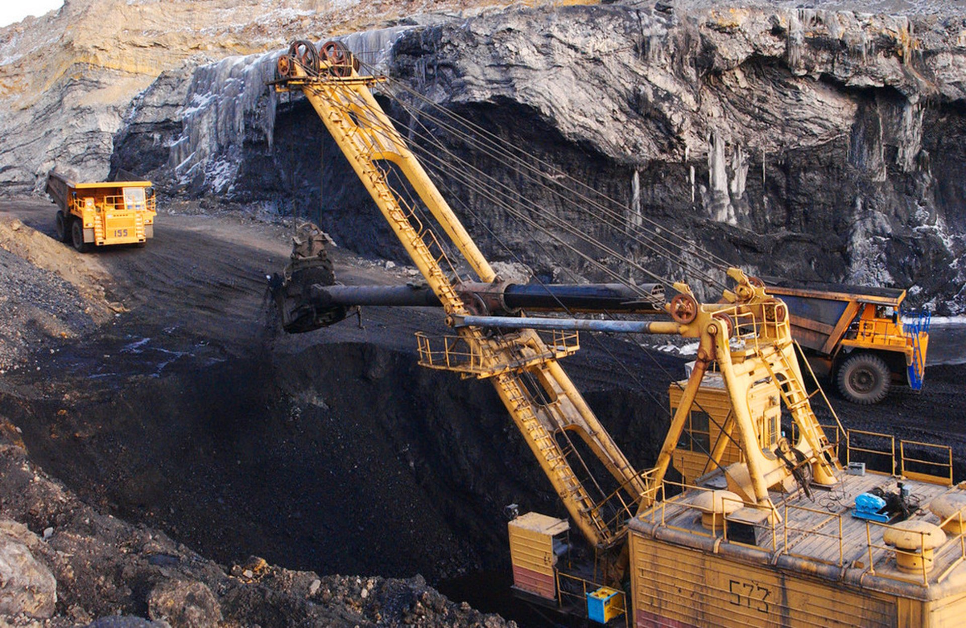
Durable mining cables for tough environments and operations
Email: Li.wang@feichuncables.com
© 2025. All rights reserved.
Company
Products
Contact
WhatsApp: +86 17333223430