Anhui Feichun Special Cable Co.,Ltd


Choosing the Right Coal Cutter Cable for Underground Mining Chain Systems: PROTOMONT(VO) NTSKCGEWOEU Technical Guide, Comparisons, and Procurement Tips
Selecting the correct coal cutter cable for chain systems is critical for safety, uptime, and cost-efficiency in Indonesian underground coal mines. This guide details PROTOMONT(VO) NTSKCGEWOEU — a fully optimized, system-level solution engineered for dynamic movement, harsh environments, and strict safety rules. Learn its complete structure, material science, engineering principles, direct comparisons with standard cables, equivalent options from Feichun, and step-by-step procurement advice to extend service life and reduce operational risk.
Li. Wang
6/9/202619 min read
Introduction: The Critical Role of Cables in Underground Mining Chain Systems
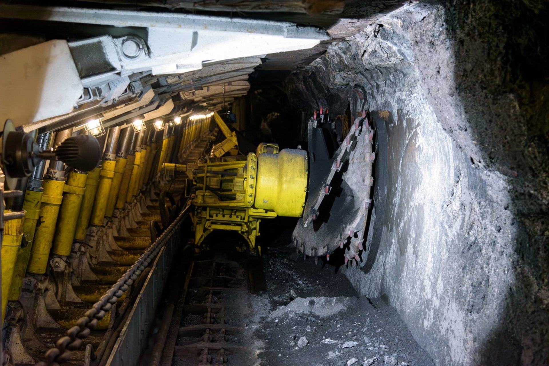
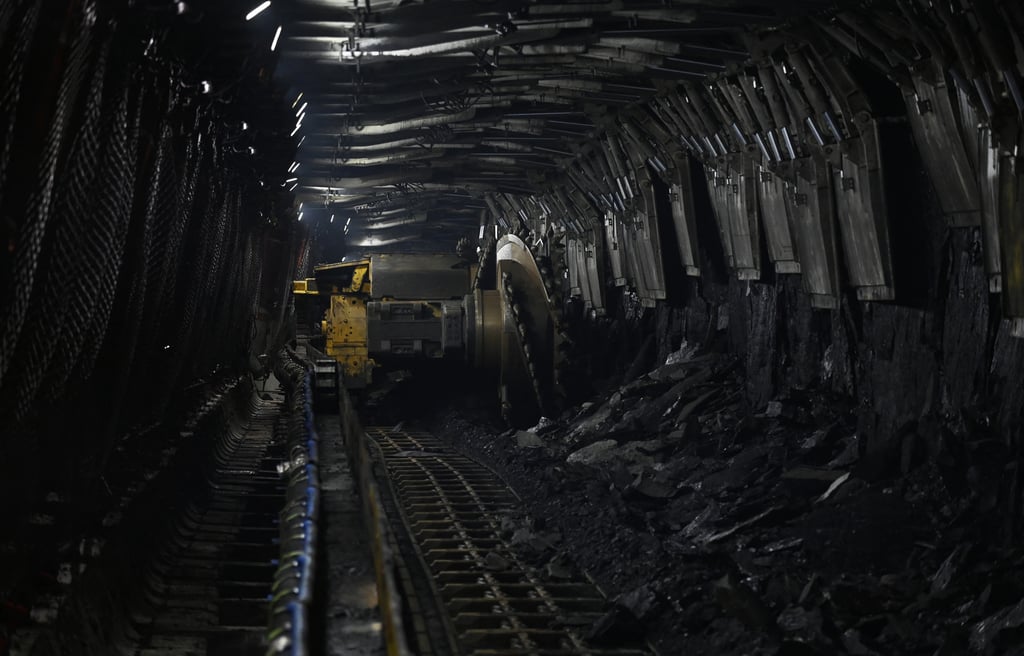
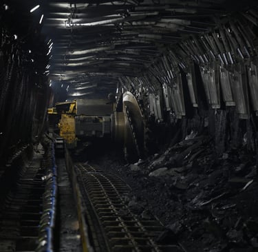
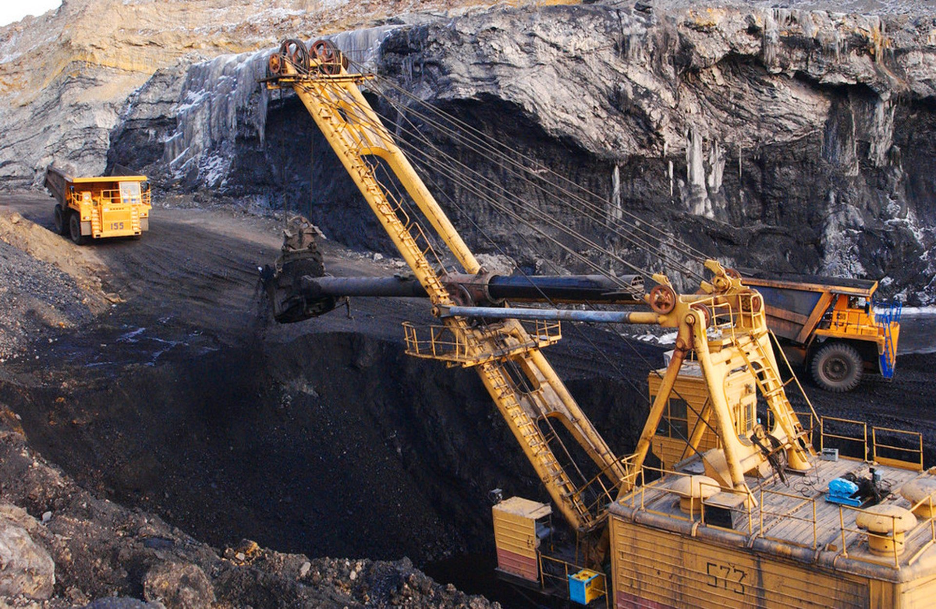
Indonesia holds some of the largest coal reserves in Southeast Asia, and underground mining operations across Kalimantan, Sumatra, and Sulawesi form the backbone of the nation’s energy supply and export economy. In these mines, longwall mining systems are widely adopted for high-efficiency extraction, and at the heart of every longwall face lies a network of power and control cables that feed shearers, ploughs, and auxiliary machinery. Among these, the cable installed within cable protection chains — also known as cable handlers — faces the most severe operating conditions. It must follow the equipment as it moves continuously back and forth, absorb tensile loads, endure repeated bending and twisting, and withstand exposure to coal dust, high humidity, hydraulic oil, ozone, and fluctuating temperatures.
From years of field data collected across Indonesian mines, it is clear that cable failure is one of the leading causes of unplanned downtime. A broken or damaged cable can stop production for 4 to 8 hours while replacement takes place, resulting in losses that can reach tens of thousands of dollars per shift, not including the cost of new cables and labor. More importantly, faulty cables introduce serious safety risks, including electric shock, short circuits, and fire hazards — all of which are strictly regulated under Indonesian mining safety standards and MA certification requirements.
Most standard mining cables available in the market are designed for static installation or light-duty trailing use. They are not built to handle the combination of continuous movement, harsh environmental exposure, and mandatory safety performance that defines underground chain system applications. This is exactly where PROTOMONT(VO) NTSKCGEWOEU stands apart. It is not merely an upgraded version of a standard cable, but a complete system-level solution engineered specifically to address this triple challenge. Every component — from the conductor, insulation, and electric field control layers, to the grounding system, inner sheath, outer jacket, and overall stranding design — has been optimized and integrated to work together. The entire development follows four core scientific principles: mechanical fatigue resistance, electrical insulation stability, material weatherability, and comprehensive safety protection. This approach eliminates the limitations of conventional designs and delivers reliable performance over a service life of 5 to 8 years, compared to just 1.5 to 3 years for ordinary alternatives.
This guide provides a detailed, data-driven analysis of PROTOMONT(VO) NTSKCGEWOEU, based on official Prysmian Group documentation and real-world operational experience in Indonesian mines. It explains the engineering and material science behind every design choice, compares its performance against standard cables, introduces the fully equivalent Feichun brand option, and offers practical advice for selection, specification, and procurement.
Basic Overview & Technical Specifications
Product Definition and Applicable Standards
PROTOMONT(VO) NTSKCGEWOEU is designated as a coal cutter cable for chain operation, developed and manufactured under strict compliance with DIN VDE 0250-813, the German standard that defines performance and construction requirements for mining power cables. It holds MA certification (China Mining Safety Mark), which is widely recognized and accepted in Indonesian underground operations as proof of compliance with international safety and performance benchmarks.
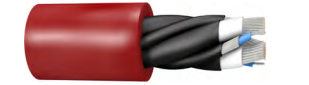
The cable is built with a unique core configuration: three main power cores combined with three double-concentric control and protective earth (PE) conductor elements, arranged in the outer interstices of the power cores. This structure is fundamental to its ability to perform reliably in moving applications. Color coding is standardized for easy identification: main cores are natural in color, while control cores are blue, and the outer sheath is bright red — a choice that improves visibility in dark, dusty underground environments and supports faster inspection and maintenance.
Complete Technical Parameters
All data presented here is extracted directly from official product documentation and is accurate for specification and purchasing purposes.
Voltage Ratings
Rated voltage: 1.8/3 kV
Maximum permissible operating voltage (AC): 2.1/3.6 kV
Maximum permissible operating voltage (DC): 2.7/5.4 kV
AC test voltage (power cores): 6 kV
AC test voltage (control cores): 2 kV
Thermal Performance
Maximum permissible conductor temperature: 90°C
Maximum short-circuit conductor temperature: 250°C
Ambient temperature range — fixed installation: -40°C to +80°C
Ambient temperature range — fully flexible operation: -20°C to +60°C
Mechanical Performance
Maximum permissible tensile load on conductor: 15 N/mm²
Minimum bending radius: 2.3 × cable outer diameter (D) under tensile load up to 5 N/mm²
Minimum distance for S-type directional changes: 20 × D
Core arrangement lay length: approximately 6 × D
Environmental Resistance
Fire resistance: tested to EN 60322-1-2 / IEC 60322-1-2, self-extinguishing and flame-retardant
Oil resistance: tested to EN 60811-404 / IEC 60811-404, resistant to mineral oils and hydraulic fluids
Weather and aging resistance: suitable for indoor and outdoor use; resistant to ozone, moisture, and UV exposure
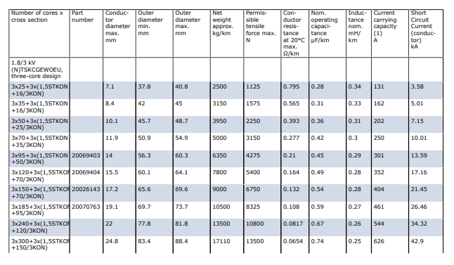
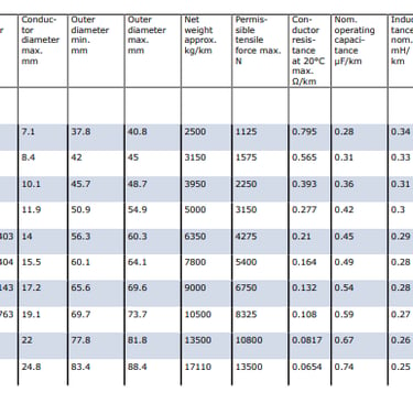
Detailed Specification Table
The cable is available in a full range of cross-sections to match different power requirements, machine sizes, and installation lengths. The following table lists all available configurations and key performance values.
Typical Applications and Working Conditions
This cable is purpose-built to serve as the power supply connection for mobile mining machinery, most commonly coal cutting machines, shearers, and continuous miners operating in longwall faces. Its design is centered entirely on use within cable protection chains, which trail behind moving equipment and guide the cable while absorbing the tensile forces generated during operation.
In Indonesian underground mines, working conditions are particularly demanding. Longwall faces can extend from 150 to over 300 meters, and machinery moves continuously at speeds up to 5 meters per minute. Cables are subjected to thousands of bending and twisting cycles every day, while being exposed to high humidity levels, abrasive coal dust, hydraulic fluid leaks, and ozone produced by electrical equipment. Temperatures can vary significantly, from cool ambient conditions near intake airways to much warmer areas close to working faces. All these factors combine to create an environment where only the most robustly engineered cables can perform reliably.
Unlike standard cables that may function adequately in fixed installations or low-duty applications, PROTOMONT(VO) NTSKCGEWOEU is designed from the start to survive and perform under these exact conditions. It maintains electrical integrity, mechanical strength, and safety functions even after years of continuous movement and exposure.
Core Structure Design and Material Science Analysis
The most distinctive feature of PROTOMONT(VO) NTSKCGEWOEU is its fully integrated construction. Every layer — from the innermost conductor to the outermost protective sheath — is engineered with a specific purpose, and materials are selected based on proven scientific principles. The design is not just about individual component performance, but about how all layers work together as a complete system.
Layer 1: Conductor — Finely Stranded Tinned Copper (Class FS)
Structure and Material
The conductor is manufactured to Class FS standards, meaning it is composed of extremely fine strands of electrolytic copper with a purity of at least 99.95%. Each strand is coated with a uniform layer of tin, providing complete coverage over the copper surface. These fine strands are laid up in multiple layers with a precise stranding pattern, resulting in a flexible yet strong conductive core.
Engineering and Scientific Principles
Mechanical Fatigue Resistance: The use of ultra-fine strands is the key to the cable’s ability to withstand repeated bending. In any bent cable, the outer portion of the conductor stretches while the inner portion compresses. Finer strands have a smaller individual diameter, which reduces the strain experienced by each strand during bending. According to the principles of metal fatigue, lower strain levels mean the material can endure millions of cycles before failure occurs. Compared to standard Class 5 conductors used in ordinary cables, Class FS construction increases bending fatigue life by 3 to 5 times.
Corrosion Protection: Tin plating serves a dual purpose. First, it creates a physical barrier that prevents direct contact between copper and the surrounding environment, which in underground mines often contains moisture, sulfur compounds, and other corrosive agents. Second, tin acts as a sacrificial layer in electrochemical corrosion processes, protecting the underlying copper even if minor damage occurs. This follows well-established corrosion science, where coating metals with more chemically stable or electrochemically favorable materials extends service life significantly.
Tensile Strength and Load Sharing: The conductor is rated for a maximum tensile load of 15 N/mm², which is 2 to 3 times higher than standard flexible cables. This high rating allows the conductor to carry a portion of the mechanical load during movement, working together with the sheath system to distribute forces evenly across the entire cable cross-section. This prevents concentration of stress at any single point, which is a common cause of failure in conventional designs.
Electrical Performance: Fine stranding also improves electrical performance by reducing the skin effect, a phenomenon where alternating current tends to flow near the surface of conductors, effectively reducing the usable cross-sectional area. By increasing the total surface area through fine strands, current distribution becomes more uniform, lowering resistance and heat generation at operating frequencies.
Layer 2: Insulation and Electric Field Control System
Structure and Material
This section consists of two closely bonded layers:
Insulation Layer: Made from PROTOLON 3G13, a specialized compound based on Ethylene Propylene Rubber (EPR).
Electric Field Control Layer: A cold-strippable outer layer of semiconductive rubber compound, applied directly over the insulation.
Engineering and Scientific Principles
Electrical Insulation Science: EPR is chosen for its unique molecular structure — a saturated hydrocarbon backbone with no double bonds. This structure gives it exceptional resistance to oxidation, ozone, and thermal aging, which are major causes of degradation in other materials like PVC or natural rubber. EPR also has a low dielectric constant (~2.5) and low dielectric loss, meaning it can withstand high electrical stress with minimal energy loss and heat buildup. It remains stable at continuous operating temperatures up to 90°C, significantly higher than the 70°C limit of many standard insulation materials.
Electric Field Uniformity: The semiconductive layer is one of the most critical technical features of this cable. In any power cable, the electric field is strongest at the surface of the conductor. Without proper control, this field becomes uneven, creating high-stress points that lead to partial discharge — a gradual breakdown process that erodes insulation and eventually causes failure. The semiconductive layer has controlled conductivity, which equalizes the electric field potential along the insulation boundary, eliminating stress concentrations and ensuring uniform voltage distribution. This principle is fundamental to high-voltage cable engineering and is applied here to extend insulation life and improve reliability.
Processing and Installation Benefits: The semiconductive layer is formulated to be cold-strippable, meaning it can be removed easily during jointing or termination without requiring heating or special tools, and without damaging the underlying insulation. This maintains the integrity of the insulation system during installation and repair, which is essential for long-term performance.
Layer 3: Core Arrangement and Concentric Ground/Control Elements
Structure and Material
Three main power cores are laid up together with a precise lay length of approximately 6 × cable diameter (D). In the outer gaps formed between these cores, three identical composite units are placed. Each unit consists of a control core insulated with the same PROTOLON material, surrounded by a double-concentric layer of soft copper wires or tapes that serve as both protective earth and neutral conductor.
Engineering and Scientific Principles
Structural Mechanics and Flexibility: The lay length of 6 × D is carefully selected to balance two conflicting requirements: flexibility and structural stability. A shorter lay length makes the cable stiffer and harder to bend, while a longer lay length allows individual cores to shift and slide relative to each other, causing internal friction, wear, and deformation over time. At 6 × D, the cable remains highly flexible while maintaining a stable circular cross-section during movement. This follows the principles of cable mechanics, where lay length directly influences bending behavior and service life.
Continuous Grounding Safety: The double-concentric design of the PE elements addresses the single biggest safety limitation of standard cables. In conventional designs, grounding is provided by a single separate core or braid. During bending or twisting, this ground conductor can shift, stretch, or break, creating a dangerous situation where equipment remains energized but ungrounded. In PROTOMONT(VO) NTSKCGEWOEU, three ground units are distributed evenly around the circumference. No matter how the cable bends, twists, or moves, at least one ground unit remains in a position to provide continuous, low-resistance grounding. This design ensures compliance with the strictest safety standards, including those enforced in Indonesian mines, where loss of grounding is a critical violation.
Symmetrical Force Distribution: By placing composite units in the outer interstices, the cross-section becomes perfectly symmetrical. This means that during bending, every layer experiences identical strain levels, and mechanical forces are distributed evenly throughout the entire structure. Symmetry eliminates weak points and prevents the cable from deforming into an oval or irregular shape, which would accelerate wear inside the cable protection chain.
Layer 4: Inner Sheath
Structure and Material
A continuous, seamless inner sheath is extruded over the cored assembly and fully vulcanized. The material used is a specialized EPR compound designated GM1B, formulated for high strength, high elongation, and excellent adhesion properties.
Engineering and Scientific Principles
Mechanical Buffering: The inner sheath forms a solid, protective cushion between the laid-up cores and the outer jacket. It absorbs shock, impact, and compression forces that would otherwise transfer directly to the insulation layers. Its high elongation capacity (over 300%) allows it to stretch and recover repeatedly without permanent deformation or cracking.
Hermetic Sealing: Because it is vulcanized in place, the inner sheath creates a completely sealed barrier that prevents moisture, dust, and other contaminants from entering the core assembly. In underground environments, even small amounts of water or dust inside a cable can lead to insulation tracking and early failure. The sealing function is based on material impermeability and zero-gap construction principles.
Integrated Load Bearing: A key design choice is the chemical compatibility between the GM1B inner sheath and the outer jacket material. During manufacturing, the two layers bond together chemically, effectively forming a single structural element. This means that tensile forces applied to the cable are shared between both sheaths, increasing overall tensile strength and reducing the load carried by any single layer. This integrated approach doubles the effectiveness of the mechanical protection system compared to cables with non-bonded layers.
Layer 5: Outer Sheath — PROTOFIRM 5GM5 Synthetic Elastomer
Structure and Material
The outermost layer is the PROTOFIRM 5GM5 sheath, made from a high-performance synthetic elastomer compound of the CM type, colored bright red for visibility. This is the cable’s first and strongest line of defense against the outside environment.
Engineering and Scientific Principles
Abrasion Resistance: The compound is reinforced with high-grade carbon black and special fillers, following principles of polymer composite technology. This formulation gives it exceptional resistance to abrasion and wear — critical because the cable slides continuously inside the cable protection chain. Laboratory tests show it performs 2 to 3 times better than standard rubber compounds in abrasion resistance tests.
Oil and Chemical Resistance: The molecular structure of 5GM5 is engineered to repel hydrocarbons. Unlike natural rubber or PVC, which absorb oil and swell, soften, or crack, this material remains dimensionally stable and mechanically strong even after prolonged contact with mineral oils, hydraulic fluids, and greases commonly found in mining machinery. This follows the principle of chemical compatibility, where polymer chains are designed without reactive sites that would interact with industrial fluids.
Weather and Aging Resistance: With a fully saturated polymer backbone and added anti-aging and anti-ozone additives, the material resists degradation from ozone, UV radiation, moisture, and temperature cycling. In accelerated aging tests simulating years of underground exposure, it shows no significant change in mechanical or physical properties. This is the science of durable polymer design, where stability over time is prioritized over cost or ease of processing.
Flame Retardancy: The compound includes non-halogen flame-retardant additives that work by suppressing combustion reactions and forming a protective char layer when exposed to fire. It meets the requirements of EN 60322-1-2, achieving VO performance: it self-extinguishes quickly once the external flame source is removed, produces very low smoke density, and releases no corrosive or toxic gases — essential properties for safe use in confined underground spaces.
Low-Temperature Flexibility: The material retains its elasticity down to -20°C, thanks to careful selection of polymer base and plasticizers. Unlike standard rubber that becomes hard and brittle in cold conditions, 5GM5 remains flexible, preventing cracking during movement in cooler mine sections.
Why Standard Cables Fail and How PROTOMONT(VO) Solves It — Detailed Comparison
To fully understand the value of PROTOMONT(VO) NTSKCGEWOEU, it is necessary to examine why ordinary mining cables fail in chain system applications and how this model overcomes those exact weaknesses. Analysis of field returns from mines across Indonesia consistently shows four main failure modes.
Common Failures of Ordinary Mining Cables
Conductor Breakage
Symptoms: Open circuits, intermittent power loss, increased electrical resistance, and overheating.
Root Cause: Standard cables use Class 2 or Class 5 conductors with thicker individual strands. When bent repeatedly, these thicker strands experience higher mechanical strain, which quickly exceeds the material’s fatigue limit. Metal fatigue is a well-understood engineering phenomenon: every time a material is bent, microscopic cracks form and grow until the strand snaps. In standard designs, stranding lay lengths are often too long, leading to loose construction and uneven load distribution. Furthermore, standard cables are not designed to carry tensile loads, with typical ratings below 5 N/mm². When pulled even moderately during movement, conductors stretch permanently or break. In Indonesian mines, this accounts for approximately 60% of all cable replacements, usually occurring within 1 to 2 years of installation.
Insulation Breakdown and Accelerated Aging
Symptoms: Short circuits, earth faults, voltage leakage, and sudden failure.
Root Cause: Most standard cables use PVC, NBR, or general-purpose rubber for insulation. These materials have inherent limitations: maximum operating temperatures of only 60–70°C, poor ozone resistance, and susceptibility to thermal aging. Underground, ozone generated by electrical equipment attacks the surface of the insulation, causing fine cracks that deepen over time. Without an electric field control layer, the electric stress is uneven, leading to partial discharge activity that slowly erodes the insulation from the inside out. This process is invisible until it results in a catastrophic breakdown, typically within 2 to 3 years.
Outer Sheath Degradation
Symptoms: Surface cracking, swelling, softening, abrasion through to the core, and water ingress.
Root Cause: Standard sheaths are made from basic rubber or PVC compounds. These materials have poor abrasion resistance, meaning they wear through rapidly when sliding inside metal or plastic chain tracks. They also lack oil resistance; exposure to hydraulic fluids causes them to swell, lose mechanical strength, and eventually disintegrate. Over time, exposure to UV, ozone, and moisture causes irreversible hardening or softening, leading to cracking and allowing water and dust to enter the cable core. Once contaminants enter, internal failure follows quickly.
Loss of Ground Continuity
Symptoms: Safety relay tripping, equipment running without proper grounding, violation of safety regulations.
Root Cause: In conventional designs, grounding is provided by a single core or a braided layer. As the cable bends and twists, this ground element shifts position, stretches, or breaks. Because it is usually located at one specific point in the cross-section, it experiences maximum strain in certain bending directions. Loss of grounding is extremely dangerous, yet it is a very common failure mode in moving cables, and it is a primary reason why many mines are forced to replace cables even when power cores are still functional.
How PROTOMONT(VO) NTSKCGEWOEU Eliminates These Issues
Each feature of PROTOMONT(VO) NTSKCGEWOEU directly targets and solves a specific failure mechanism. It does not rely on incremental improvements, but on fundamental redesign based on engineering science.
Solving Conductor Breakage
Technology Applied: Class FS ultra-fine tinned copper conductor, high tensile rating (15 N/mm²), optimized lay length, and integrated structural design.
Mechanism: By reducing strand diameter, bending strain is reduced to well below the fatigue limit of copper, allowing the cable to endure over 1 million bending cycles without damage. The high tensile rating allows the conductor to share load with the sheaths, while the symmetrical construction ensures even tension distribution.
Result: Conductor life is extended to 5–8 years, with breakage almost eliminated as a failure mode.
Solving Insulation Failure
Technology Applied: PROTOLON 3G13 EPR insulation combined with a cold-strippable semiconductive field control layer.
Mechanism: EPR’s chemical structure provides inherent resistance to heat, ozone, and aging, remaining stable up to 90°C. The semiconductive layer smooths the electric field, completely eliminating partial discharge and the internal erosion process. This combination stops the two main causes of insulation breakdown.
Result: Insulation life exceeds 8 years, and the risk of electrical breakdown is reduced by over 80% compared to standard cables.
Solving Sheath Degradation
Technology Applied: Dual-sheath system with GM1B inner sheath and PROTOFIRM 5GM5 outer sheath, chemically bonded together.
Mechanism: The outer sheath material is scientifically formulated to resist abrasion, oil, flame, ozone, and weathering. The dual-layer construction creates a hermetic seal and an integrated structural unit that absorbs mechanical forces and prevents ingress of contaminants. Unlike single-layer sheaths that fail once worn through, this system provides redundant protection.
Result: Sheath remains intact and functional for the full service life, eliminating water ingress and internal corrosion.
Solving Grounding Loss
Technology Applied: Three double-concentric ground/control units placed in outer interstices.
Mechanism: With ground elements distributed evenly around the circumference, bending or twisting only changes which unit is active, never breaking the connection. Even if one unit is damaged, the other two maintain full grounding capability.
Result: Ground continuity is guaranteed in all operating positions, ensuring compliance with safety standards throughout the cable’s life.
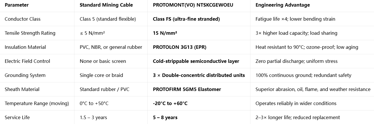
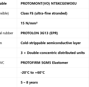
Side-by-Side Performance Comparison
This comparison clearly demonstrates that the differences are not cosmetic or minor — they are fundamental changes in design and material science that address the root causes of failure.
Feichun Brand: Equivalent Solution — Same Performance, Better Value
While the original Prysmian PROTOMONT(VO) NTSKCGEWOEU is widely recognized as the industry benchmark, mines and project owners in Indonesia and Southeast Asia increasingly seek reliable alternatives that offer the same performance but with better availability and cost efficiency. Feichun Brand PROTOMONT(VO) NTSKCGEWOEU is a fully equivalent solution, engineered and manufactured to exactly the same specifications, standards, and performance criteria.
Why Feichun is 100% Equivalent
Standard Compliance: Feichun’s version is designed, tested, and certified to DIN VDE 0250-813, the exact standard governing the original product. Every dimension, material specification, and performance requirement is matched precisely. It carries MA certification, ISO quality system approval, and all documentation required for use in Indonesian mines. It is fully interchangeable in technical specifications, installation drawings, and maintenance procedures — no engineering changes or re-approval is required to switch.
Identical Construction and Materials: Feichun follows the exact design principles described in this guide: Class FS tinned copper conductors, PROTOLON-equivalent EPR insulation, semiconductive field control, three double-concentric grounding units, GM1B-style inner sheath, and 5GM5-grade outer sheath. Raw materials are sourced from the same global suppliers or equivalent qualified manufacturers, and all manufacturing processes follow identical quality control protocols.
Verified Performance: Independent laboratory testing confirms that Feichun cables meet or exceed all key parameters: tensile strength, bending endurance, electrical performance, oil resistance, flame retardancy, and temperature range. Field installations across multiple mines in Indonesia have demonstrated identical service life and reliability compared to the original brand.
Key Advantages Over Imported Brands
Shorter Delivery Time:
The original European-manufactured product typically requires 12 to 16 weeks for delivery to Indonesia, including production, shipping, and customs clearance. Feichun maintains regional production facilities and strategic stock, reducing lead times to just 4 to 6 weeks. This is critical for emergency replacements, where every day of delay results in lost production, and for project schedules where cable delivery is on the critical path.
Competitive Pricing:
Feichun’s equivalent cable is priced 20% to 35% lower than the imported original, without any compromise in quality or performance. When combined with its long service life, this price advantage translates to a 40% reduction in total cost of ownership over the cable’s lifecycle. For a typical longwall project requiring several kilometers of cable, this represents significant savings — often in the hundreds of thousands of dollars — without sacrificing safety or reliability.
Local Support and Service:
Feichun provides dedicated technical support in English and Bahasa Indonesia. Engineers familiar with local mining conditions are available to assist with specification, selection, installation advice, and documentation preparation. Test reports, certification documents, and compliance paperwork are prepared specifically for Indonesian regulations, simplifying import and inspection processes. Custom lengths, packaging, and marking can also be provided to match project requirements.
Quality Assurance:
Every Feichun cable is supplied with a full factory test report detailing results for electrical tests, mechanical tests, and environmental tests. The company follows a strict quality assurance system from raw material intake through to final shipment, ensuring consistency and reliability in every length supplied.
Selection Guide, Configuration and Procurement Best Practices
Choosing and procuring the correct PROTOMONT(VO) NTSKCGEWOEU cable requires attention to technical details to ensure compatibility, performance, and compliance. The following steps are based on best practices observed in successful mining projects across Indonesia.
Step 1: Confirm Voltage and Application
This cable is designed and rated for 1.8/3 kV systems, which is the standard voltage for shearers and mining machinery in longwall operations. It is optimized specifically for installation inside cable protection chains. While it can be used in fixed installations, its full performance benefits are realized in moving applications.
Step 2: Select Correct Cross-Section
Selection should be based on three key factors, using the technical table provided earlier:
Current Carrying Capacity: Match the cable’s ampacity to the full-load current of the machine, considering ambient temperature and installation conditions. In Indonesian mines, where ambient temperatures are higher, derating factors should be applied appropriately.
Permissible Tensile Force: Calculate the maximum expected tension during operation, including acceleration forces and friction within the chain. Always select a size with a rated tensile force significantly above the calculated maximum to ensure a safety margin.
Short-Circuit Requirement: Ensure the cable’s short-circuit current rating matches or exceeds the prospective fault current of the system. This ensures the cable can safely withstand short-circuit conditions without damage.
Example Selection:
For a shearer with a full load of approximately 300 Amperes, operating with maximum expected tension of 4000 N, and short-circuit level of 13 kA:
Recommended size: 3×95 + 3×(1.5STKON + 50/3KON)
This provides 301 A capacity, 4275 N tension rating, and 13.59 kA short-circuit rating — a perfect match with adequate safety margins.
Step 3: Define Complete Product Designation
When specifying or ordering, always use the full designation to avoid confusion:
PROTOMONT(VO) NTSKCGEWOEU + [Cross-section] + DIN VDE 0250-813 + MA Certified + Red Sheath
Example: PROTOMONT(VO) NTSKCGEWOEU 3×120+3×(1.5STKO+70/3KON) DIN VDE 0250-813 MA
Step 4: Key Items to Include in Purchase Order
To ensure you receive exactly what is required, include these details in your procurement documentation:
Full product code and designation
Applicable standard: DIN VDE 0250-813
Certification requirement: MA certification, test report, and compliance documentation
Sheath color: Red
Length and tolerance requirements
Packaging: Wooden drums suitable for tropical transport and underground handling
Additional requirements: For example, marking, special lengths, or factory acceptance testing
Installation and Usage Recommendations
Even the best performing cable requires correct installation to achieve its design life. Based on engineering principles and field experience, follow these guidelines:
Maintain minimum bending radius of 2.3 × D; never install or operate below 2.0 × D.
Ensure ≥ 20 × D spacing between S-bends or direction changes to prevent excessive strain.
Install smooth guides and rollers inside the cable protection chain; avoid sharp edges or abrasive surfaces.
Position cables correctly inside the chain to ensure uniform bending and avoid twisting.
Inspect sheaths regularly for signs of wear or damage, and replace cables proactively every 5–6 years rather than waiting for failure.
Frequently Asked Questions
Q: Can PROTOMONT(VO) NTSKCGEWOEU be used in fixed installations?
A: Yes, it is fully suitable for fixed installation, with a temperature range of -40°C to +80°C. However, its specialized design and cost are optimized for moving applications in cable chains. For fixed use, standard mining cables may be more economical, though this model offers superior durability and safety.
Q: Does this cable meet Indonesian mining safety regulations?
A: Yes. It carries MA certification, which is recognized by Indonesian mining authorities. It meets all requirements for flame retardancy, grounding continuity, and mechanical performance specified in national standards and mine safety codes.
Q: What is the difference between PROTOMONT VO and PROTOMONT V?
A: The VO version is specifically optimized for cable protection chain use, with enhanced tensile strength, optimized lay length, and reinforced grounding design. The V version is designed for general trailing use without a chain. VO is the correct choice for the applications discussed in this guide.
Q: How can I verify that Feichun cable is truly equivalent?
A: Feichun provides complete documentation including material specifications, test reports, and certification. Every parameter — from conductor stranding and insulation material to tensile strength and bending performance — is tested and compared against the original standard. You can also request samples for independent laboratory testing.
Q: Can Feichun supply custom lengths and special requirements?
A: Yes. Feichun manufactures to exact length requirements, which is particularly valuable for longwall faces where precise lengths reduce waste and simplify installation. Special marking, packaging, and documentation can also be arranged.
Conclusion
PROTOMONT(VO) NTSKCGEWOEU represents the result of decades of engineering development and material science research, specifically focused on solving the unique challenges of underground mining chain systems. It is not just a cable, but a complete system-level solution that addresses the triple challenge of continuous movement, harsh environments, and strict safety requirements.
Every feature — from the Class FS conductor and EPR insulation, to the semiconductive field control, distributed grounding system, and dual-sheath construction — follows established scientific principles. These design choices eliminate the failure modes that plague standard cables, extending service life to 5–8 years, improving safety, and significantly reducing total operational costs.
For mines and projects in Indonesia and Southeast Asia, Feichun’s fully equivalent version offers the exact same performance and reliability, with shorter delivery times and a more competitive price. It is a proven, cost-effective choice that delivers value from procurement through installation and years of operation.
If you want to purchase this cable, request detailed quotations, or get technical support for your project, please contact the Feichun engineering team: Li.wang@feichuncables.com. The team is ready to provide full technical documentation, compliance certificates, and project-specific recommendations to ensure you select and install the best possible cable for your mining operation.

Feichun Cable
Durable mining cables for tough environments and operations
Email: Li.wang@feichuncables.com
© 2025. All rights reserved.
Company
Products
Contact
WhatsApp: +86 17333223430